Mitsubishi Colt Ralliart. Manual — part 129

EMISSION CONTROL
ENGINE AND EMISSION CONTROL
17-7
<4G1>
AK600530AB
Canister
Purge control
solenoid valve
Fuel pressure control
solenoid valve
Check valve
Waste gate
solenoid valve
Waste gate
actuator
Air
inlet
Catalytic
converter
Catalytic
converter
Injector
From
fuel pump
Fuel pressure
regulator
To
fuel tank
Oxygen sensor
(front)
Oxygen sensor
(rear)
Main
Index
Group
TOC
EMISSION CONTROL
ENGINE AND EMISSION CONTROL
17-8
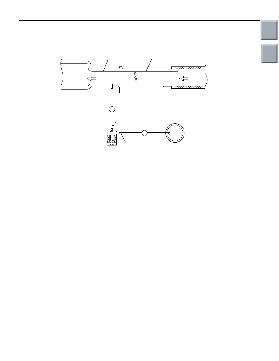
VACUUM CIRCUIT DIAGRAM
M1173007100702
<4A9>
AK304617
From
air
cleaner
To
combustion
chamber
Throttle body
B
B
Intake manifold
Purge
control
solenoid
valve
Canister
Vacuum hose colour
B: Black
AB
R mark (stamp)
W mark (stamp)
Main
Index
Group
TOC
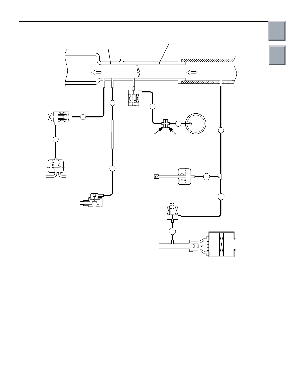
EMISSION CONTROL
ENGINE AND EMISSION CONTROL
17-9
<4G1>
AK402415
Vacuum hose colour
B:Black
L:Light blue
R:Red
W:White
Air cleaner
AB
W
B
L
B
B
B
Waste gate
solenoid valve
Waste gate actuator
Canister
Check valve
Purge control
solenoid valve
Air by-pass valve
Fuel pressure regulator
Fuel pressure
control solenoid valve
To
combustion
chamber
From
air
cleaner
Throttle body
Intake manifold
Black
Brown
B
R
B
B
VACUUM HOSE CHECK
M1173007300397
1. Using the piping diagram as a guide, check to be
sure that the vacuum hoses are correctly
connected.
2. Check the connection condition of the vacuum
hoses, (removed, loose, etc.) and check to be
sure that there are no bends or damage.
VACUUM HOSE INSTALLATION
M1173007200312
1. When connecting the vacuum hoses, they should
be securely inserted onto the nipples.
2. Connect the hoses correctly, using the vacuum
hose piping diagram as a guide.
Main
Index
Group
TOC

EMISSION CONTROL
ENGINE AND EMISSION CONTROL
17-10
CRANKCASE EMISSION CONTROL
SYSTEM
GENERAL INFORMATION (CRANKCASE
EMISSION CONTROL SYSTEM)
M1173005000817
The crankcase emission control system prevents
blow-by gases from escaping inside the crankcase
into the atmosphere.
Fresh air is sent from the air cleaner into the crank-
case through the breather hose.
The air becomes mixed with the blow-by gases
inside the crankcase.
The blow-by gas inside the crankcase is drawn into
the inlet manifold through the positive crankcase
ventilation (PCV) valve.
The PCV valve lifts the plunger according to the inlet
manifold vacuum so as to regulate the flow of
blow-by gas properly.
In other words, the blow-by gas flow is regulated dur-
ing low load engine operation to maintain engine sta-
bility, while the flow is increased during high load
operation to improve the ventilation performance.
SYSTEM DIAGRAM
<4A9-M/T>
AK600608
PCV valve
AB
Ventilation hose
Breather hose
Air cleaner
Main
Index
Group
TOC
Нет комментариевНе стесняйтесь поделиться с нами вашим ценным мнением.
Текст