Mitsubishi Colt Ralliart. Manual — part 206

GROUP 33
FRONT
SUSPENSION
CONTENTS
GENERAL INFORMATION . . . . . . . .
SERVICE SPECIFICATIONS. . . . . . .
LUBRICANT. . . . . . . . . . . . . . . . . . . .
SPECIAL TOOLS. . . . . . . . . . . . . . . .
ON-VEHICLE SERVICE. . . . . . . . . . .
FRONT WHEEL ALIGNMENT CHECK
AND ADJUSTMENT . . . . . . . . . . . . . . . . . .
LOWER ARM BALL JOINT AXIAL PLAY
CHECK . . . . . . . . . . . . . . . . . . . . . . . . . . . .
LOWER ARM BALL JOINT COVER
CHECK . . . . . . . . . . . . . . . . . . . . . . . . . . . .
STRUT ASSEMBLY . . . . . . . . . . . . . .
REMOVAL AND INSTALLATION . . . . . . . .
INSPECTION. . . . . . . . . . . . . . . . . . . . . . . .
DISASSEMBLY AND REASSEMBLY . . . . .
INSPECTION. . . . . . . . . . . . . . . . . . . . . . . .
LOWER ARM . . . . . . . . . . . . . . . . . . .
REMOVAL AND INSTALLATION <4A9> . .
REMOVAL AND INSTALLATION <4G1> . .
INSPECTION. . . . . . . . . . . . . . . . . . . . . . . .
LOWER ARM BALL JOINT COVER
REPLACEMENT . . . . . . . . . . . . . . . . . . . . .
STABILIZER BAR. . . . . . . . . . . . . . . .
REMOVAL AND INSTALLATION <4A9> . .
REMOVAL AND INSTALLATION <4G1> . .
INSPECTION. . . . . . . . . . . . . . . . . . . . . . . .
WANINGS REGARDING SERVICING OF SUPPLEMENTAL RESTRAINT SYSTEM (SRS) EQUIPPED VEHICLES
WARNING
•
Improper service or maintenance of any component of the SRS, or any SRS-related component, can lead to
personal injury or death to service personnel (from inadvertent firing of the air bag) or to the driver and
paassenger (from rendering the SRS inoperative).
•
Service or maintenance of any SRS component or SRS-related component must be performed only at an
authorized MITSUBISHI dealer.
•
MITSUBISHI dealer personnel must thoroughly review this manual, and especially its GROUP 52B - Supplemental
Restraint System (SRS) before beginning any service or maintenance of any component of the SRS or any
SRS-related component.
NOTE
The SRS includes the following components: SRS air bag control unit, SRS warning light, front impact sensors, air bag module,
clock spring, and interconnecting wiring. Other SRS-related components (that may have to be removed/installed in connection
with SRS service or maintenance) are indicated in the table of contents by an asterisk (*).
Main
Index
GENERAL INFORMATION
FRONT SUSPENSION
33-2
GENERAL INFORMATION
M1332000100764
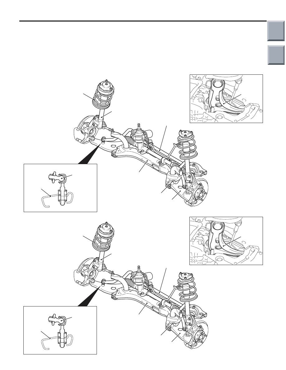
The front suspension is a MacPherson strut with coil
spring. The shock absorber is gas-filled hydraulic
double-acting type.
CONSTRUCTION DIAGRAM
AC402422 AF
<4A9>
A-point bushing
Stabilizer bar
Coil spring
Strut assembly
Lower arm
Front axle No.1 crossmember
(Flat crossmember)
Lower arm
Ball joint
Lower arm
close
section
AC402422AE
<4G1>
A-point bushing
Stabilizer bar
Coil spring
Strut assembly
Lower arm
Front axle No.1 crossmember
(Flat crossmember)
Lower arm
Ball joint
AC207732
Lower arm
close
section
Main
Index
Group
TOC

SERVICE SPECIFICATIONS
FRONT SUSPENSION
33-3
SPECIFICATIONS
COIL SPRING
<4A9>
Item
Specification
Wire diameter mm
12
Average outside diameter mm
133
− 149 − 154
Free length mm
CVT
331
5MT
301
<4G1>
Item
Specification
Wire diameter mm
13
Average outside diameter mm
133
− 150 − 154
Free length mm
300
SERVICE SPECIFICATIONS
M1332000300898
Item
Standard value
Toe-in
At the centre of tyre tread mm
0
± 2
Toe-angle (per wheel)
0
°00' ± 0°06'
Steering angle
Inner wheel
Vehicles with 14-inch
wheels
41
°40' ± 1°30'
Vehicles with 15-inch
wheels
39
°00' ± 1°30'
Vehicles with 16-inch
wheels
34
°10' ± 1°30'
Outer wheel
<reference>
Vehicles with 14-inch
wheels
35
°30'
Vehicles with 15-inch
wheels
33
°40'
Vehicles with 16-inch
wheels
30
°00'
Camber
4A9
− 0°30' ± 0°30' *
4G1
− 0°30' ± 0°45' *
Caster
4A9
2
°35' ± 0°30' *
4G1
2
°40' ± 0°45' *
Kingpin inclination
13
°20' ± 0°30'
Lower arm ball joint starting torque N
⋅m
0
− 3.9
Protruding length of stabilizer link thread part mm <4A9>
19
± 1.5
Protruding length of stabilizer link assembly mm <4G1>
5.0
± 1.5
NOTE: *: Difference between right and left wheels must be less than 30'
Main
Index
Group
TOC

LUBRICANT
FRONT SUSPENSION
33-4
LUBRICANT
M1332000400378
Item
Specified lubricant
Quantity
Bump rubber
Contact surface
between the bump
rubber and the spring
upper seat
Multipurpose grease SAE J310,
NLGI No.2 or equivalent
As required
Lower arm ball joint
<4A9>
Inside of dust cover
Inside of dust cover :
9.0
± 0.5 g
Lip portion of dust cover
Lip portion of dust
cover : 1.0
± 0.5 g
SPECIAL TOOLS
M1332000600651
Tool
Number
Name
Use
MB991004
MB991004
Wheel alignment gauge
attachment
Wheel alignment
measurement <Vehicles
with aluminium wheels>
MB991237
A
B
A: MB991237
B: MB991238
A: Spring compressor
body
B: Arm set, large
Coil spring compression
MB990326
MB990326
Preload socket
Lower arm ball joint
starting torque check
MB991680
A
B
MB991680
A: MB991681
B: MB991682
Wrench and socket set
A: Wrench
B: Socket
Strut assembly
disassembly and
reassembly
Main
Index
Group
TOC
Нет комментариевНе стесняйтесь поделиться с нами вашим ценным мнением.
Текст