Mitsubishi Colt Ralliart. Manual — part 204

ATF WARMER (ATF COOLER)
CVT
23A-159
ATF WARMER (ATF COOLER)
REMOVAL AND INSTALLATION
M1231204800048
Pre-removal and Post-installation Operation
• Air cleaner intake duct (Refer to GROUP 15 − Air Cleaner
).
• Engine coolant draining and refilling (Refer to GROUP 14
− On-vehicle Service − Engine Coolant Replacement
).
• Transmission fluid refilling (Refer to
AC403913
1
2
3
4
5
6
7
AC
23 ± 3 N·m
23 ± 3 N·m
8
9
N
1.5 ± 0.3 N·m
Removal steps
1.
Coolant feed hose
2.
Coolant return hose
3.
ATF feed hose
4.
ATF return hose
5.
ATF warmer (ATF cooler)
6.
ATF warmer (ATF cooler) bracket
7.
Thermo valve
8.
Breather plug
9.
O-ring
Removal steps (Continued)
Main
Index
Group
TOC
ATF WARMER (ATF COOLER)
CVT
23A-160
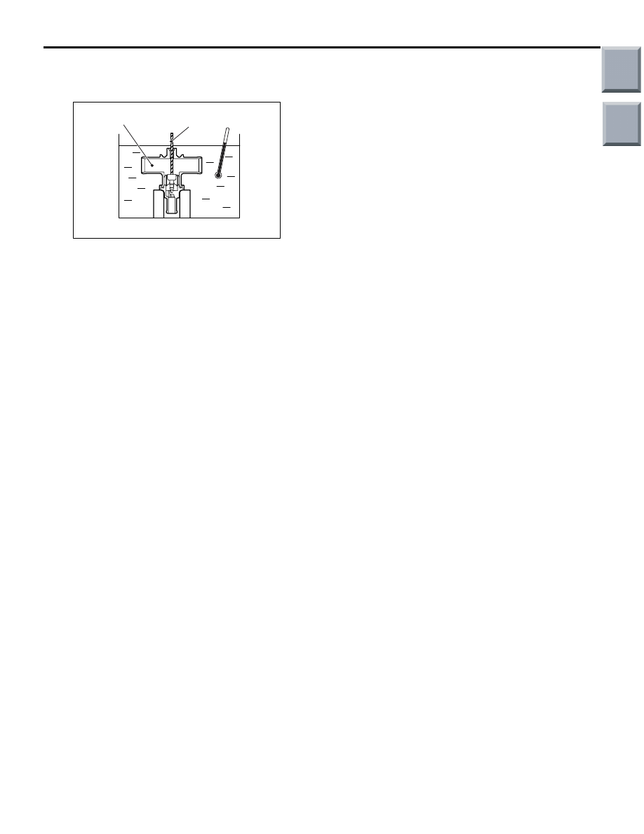
THERMO VALVE CHECK
M1231204900056
1. Remove the thermo valve breather plug.
AC403567
AC
Thermo valve
(section view)
Stick (approximately
6 mm in diameter)
2. Obtain a container which is full of water, and insert
a stick (approximately 6 mm in diameter) to the
thermo valve. While stirring the water, raise the
water temperature and check that the valve
opening temperature of the thermo valve is within
the standard value. The stick rises when the
thermo valve opens.
Standard value: 75
°C ± 1.5°C
3. When the water temperature is raised to the fully
open temperature, check that the valve lift amount
is within the standard value.
Standard value: Opening temperature 88
°C
Valve lift amount when it is fully opened: 3
mm or more
NOTE: Measure the height of the fully closed
valve in advance, and then measure the valve
height at opening temperature to calculate the
valve lift amount.
Main
Index
Group
TOC
GROUP 34
REAR SUSPENSION
CONTENTS
GENERAL INFORMATION . . . . . . . .
SERVICE SPECIFICATIONS. . . . . . .
SPECIAL TOOLS. . . . . . . . . . . . . . . .
ON-VEHICLE SERVICE. . . . . . . . . . .
REAR WHEEL ALIGNMENT CHECK AND
ADJUSTMENT . . . . . . . . . . . . . . . . . . . . . .
SHOCK ABSORBER AND
COIL SPRING . . . . . . . . . . . . . . . . . . .
REMOVAL AND INSTALLATION . . . . . . . .
TORSION AXLE ARM ASSEMBLY . .
REMOVAL AND INSTALLATION . . . . . . . .
INSPECTION. . . . . . . . . . . . . . . . . . . . . . . .
Main
Index

GENERAL INFORMATION
REAR SUSPENSION
34-2
GENERAL INFORMATION
M1341000100944
A H-shaped torsion beam suspension has been
adopted as the rear suspension. The shock absorber
is a hydraulic, cylindrical double-acting type.
CONSTRUCTION DIAGRAM
AC206930AC
Coil spring
Shock absorber
Torsion beam and arm assembly
Arm bushing
SPECIFICATION
COIL SPRING
Item
4A9
4G1
Wire diameter mm
10
11
Average outside diameter mm
75
− 107 − 75
111
Free length mm
301
283
SERVICE SPECIFICATIONS
M1341000300517
Item
Standard value
Camber
−1°00' ± 0°45' *
Toe-in
At the centre of tyre tread mm
3
± 3
Toe-angle (per wheel)
0
°09' ± 0°09'
Thrust angle
0
°00' ± 0°15'
NOTE: *: Difference between right and left wheels must be less than 30'
Main
Index
Group
TOC
Нет комментариевНе стесняйтесь поделиться с нами вашим ценным мнением.
Текст