Mitsubishi Colt Ralliart. Manual — part 596
GENERAL INFORMATION
CLUTCH
21A-2
GENERAL INFORMATION
M1211000100331
Due to the addition of vehicles with M/T, the following
service procedures for the clutch have been estab-
lished.
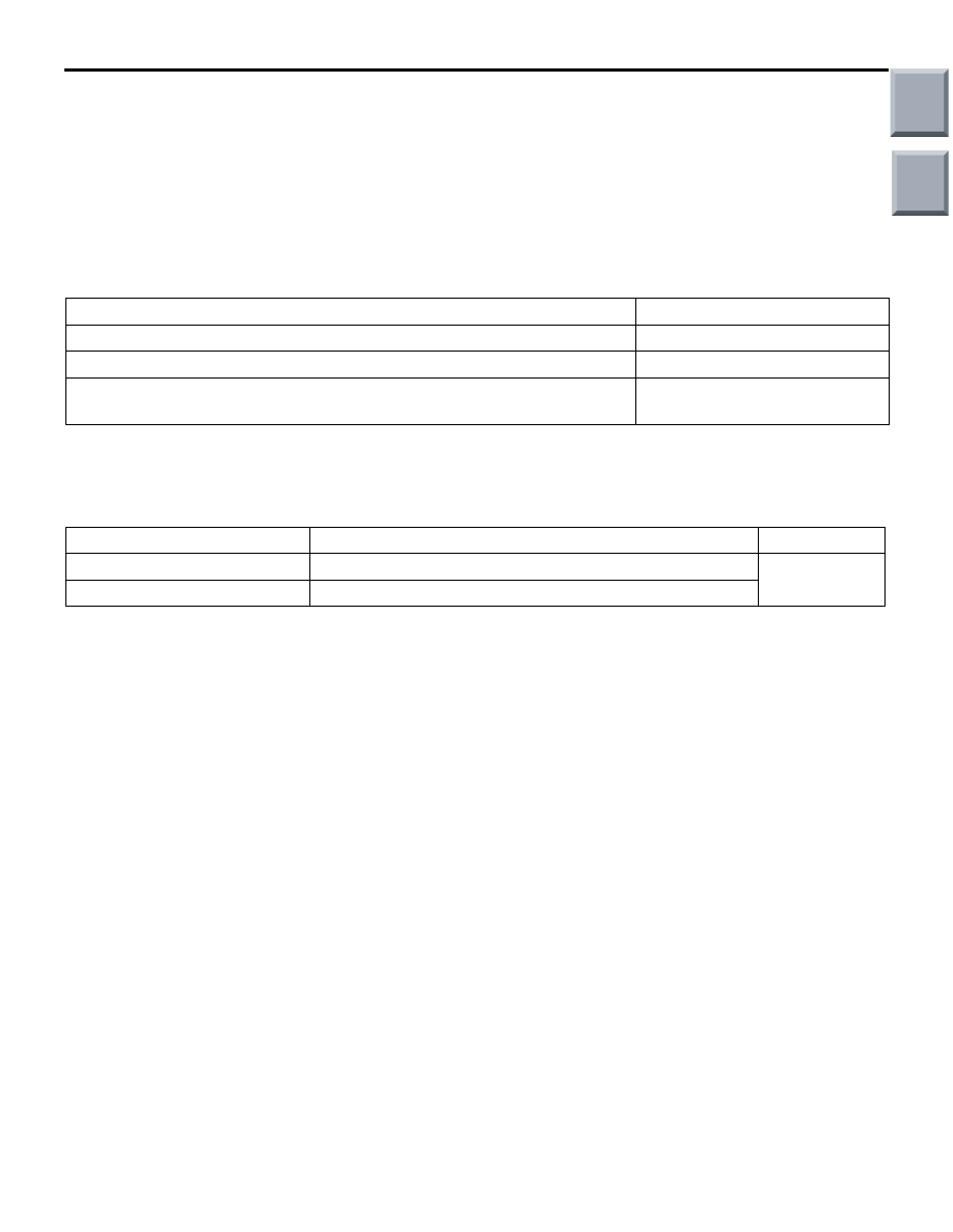
SERVICE SPECIFICATIONS
M1211000300465
Item
Standard value
Clutch pedal lateral play mm
1.5 or less
Clutch pedal height mm
147.8
± 2
Distance between the clutch pedal and the toeboard when the clutch is
disengaged mm
77 or more
LUBRICANTS
M1211000400280
Item
Specified lubricant
Quantity
Clutch fluid
Brake fluid DOT4 +
As required
Release cylinder push rod
Castrol Olista Longtime 3 EP
Main
Index
Group
TOC

ON-VEHICLE SERVICE
CLUTCH
21A-3
ON-VEHICLE SERVICE
CLUTCH PEDAL CHECK AND
ADJUSTMENT
M1211000900508
NOTE: This clutch pedal assembly is unadjustable
because of its structure.
AC601326AB
A
1. Measure the clutch pedal looseness (A).
Standard value (A): 1.5 mm or less
2. When the clutch pedal looseness is not within the
standard value, the clutch pedal assembly or the
clutch master cylinder may be faulty. In this case,
check the clutch pedal assembly or the clutch
master cylinder, and replace it if necessary.
3. Turn up the floor carpet under the clutch pedal.
AC311474 AC
B
AC311475AC
C
4. Check that the clutch pedal height (B) and the
clearance (C) between the clutch pedal and the
toe board when the clutch is disengaged are
within the standard value.
Standard value (B): 147.8
± 2 mm
Standard value (C): 77 mm or more
5. When the clutch pedal height and the clearance
between the clutch pedal and toe board when the
clutch is disengaged are not within the standard
value, the air may be intruded into the hydraulic
system, or either the clutch master cylinder or the
clutch release cylinder may be faulty. In this case,
perform air bleeding, or check the clutch master
cylinder or the clutch release cylinder, and replace
it if necessary.
CLUTCH BLEEDING
M1211001400379
CAUTION
Use the clutch fluid with the specified brand
name. Do not mix the fluid with others.
Specified fluid: Brake fluid DOT 4 +
CAUTION
When the air breather is tightened by the exces-
sive torque, the clutch release cylinder may be
damaged. Always tighten the air breather within
the standard torque.
Specified torque: 5.5
± 0.5 N⋅m
AC311339
AC
Perform air bleeding of the clutch line from the air
breather section shown in the figure.
Main
Index
Group
TOC

ON-VEHICLE SERVICE
CLUTCH
21A-4
CLUTCH PEDAL SWITCH CHECK AND
ADJUSTMENT
M1211001100259
1. Remove the clutch pedal switch.
AC601101AB
Open
circuit
8.0 0.35 mm
Less than 2 ohms
2. Check for continuity between the terminals of the
switch.
Inspection status
Normal
conditions
Do not press the plunger section.
Open circuit
Press the plunger section until it
reaches to the value shown in the
figure.
Less than 2
ohms
CLUTCH MONITOR SWITCH CHECK AND
ADJUSTMENT
M1211004900027
1. Remove the clutch monitor switch.
AC601357
1 2 3
4 5 6
AC
4.0 6.1 mm
(Open circuit)
6.0 7.0 mm
0.9 2.0
mm
(Less than 2 ohms)
2. Check the continuity for clutch monitor switch.
Tester
connection
terminal
Inspection status
Normal
conditions
1
− 6
Do not press the plunger
section.
Open
circuit
Press the plunger section
until it reaches to the
value shown in the
figure.
Less than 2
ohms
Main
Index
Group
TOC
CLUTCH PEDAL
CLUTCH
21A-5
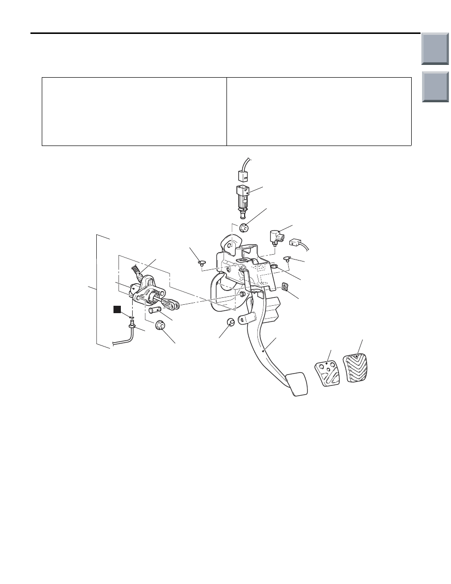
CLUTCH PEDAL
REMOVAL AND INSTALLATION
M1211001600533
Pre-removal Operation
• Clutch Fluid Draining
• Engine Cover Removal (Refer to GROUP 11A, Cam-
shaft
<4A9> or GOROUP 11C, Camshaft and
<4G1>).
• Strut Tower Bar Removal (Refer to GROUP 42, Strut
Tower Bar
).
Post-installation Operation
• Clutch Fluid Supplying
• Clutch Line Bleeding (Refer to
• Strut Tower Bar Installation (Refer to GROUP 42, Strut
Tower Bar
).
• Engine Cover Installation (Refer to GROUP 11A, Cam-
shaft
<4A9> or GOROUP 11C, Camshaft and
Valve stem seal
<4G1>).
AC600645
1
2 <4G1>
3
4
5
6
7
8
9
10
11
12
13 <4G1>
AC
N
12 ± 2 N·m
12 ± 2 N·m
24 ± 4 N·m
13 <4A9>
Removal steps
•
Reservoir hose connection <Brake
side>
1.
Clutch switch
>>
B
<<
2.
Clutch monitor switch
<<
A
>>
>>
A
<<
3.
Clutch pipe assembly A connection
•
Lower panel (Refer to 52A,
Instrument panel assembly
).
4.
Reservoir hose
5.
Clutch pedal assembly and clutch
master cylinder
6.
Clutch master cylinder clip
7.
Clutch master cylinder pin
8.
Clutch master cylinder
9.
Pedal stopper
10. Pedal stopper
11. Pedal stopper
12. Clutch pedal assembly
13. Pedal pad
Removal steps (Continued)
Main
Index
Group
TOC
Нет комментариевНе стесняйтесь поделиться с нами вашим ценным мнением.
Текст