Mitsubishi Colt Ralliart. Manual — part 544

TROUBLESHOOTING
SUPPLEMENTAL RESTRAINT SYSTEM (SRS)
52B-14
DIAGNOSTIC TROUBLE CODE
PROCEDURES
Code No.1A Front impact sensor LH system (short circuit in the sensor)
Code No.1B Front impact sensor LH system (open circuit in the sensor)
Code No.1C Front impact sensor LH system (short circuited in the power supply)
Code No.1D Front impact sensor LH system (short circuited in the earth)
Code No.2A Front impact sensor RH system (short circuit in the sensor)
Code No.2B Front impact sensor RH system (open circuit in the sensor)
Code No.2C Front impact sensor RH system (short circuited in the power supply)
Code No.2D Front impact sensor RH system (short circuited in the earth)
OPERATION
• When the left and right front impact sensors
detect a collision, the switches inside the sensors
turn ON.
• SRS-ECU judges how severe a collision is by
detecting signals from the front impact sensors
and the front air bag analogue G-sensor. If the
impact is over a predetermined level, the
SRS-ECU sends an ignition signal. At this time, if
the front air bag safing G-sensor is on, the SRS
air bag will inflate.
AC510220
SRS-ECU
FRONT IMPACT
SENSOR (RH)
FRONT IMPACT
SENSOR (LH)
Wire colour code
B : Black LG : Light green G : Green L : Blue W : White Y : Yellow SB : Sky blue
BR : Brown O : Orange GR : Grey R : Red P : Pink V : Violet
Front Impact Sensor Circuit
AB
Main
Index
Group
TOC

TROUBLESHOOTING
SUPPLEMENTAL RESTRAINT SYSTEM (SRS)
52B-15
DIAGNOSIS CODE SET CONDITIONS
These diagnosis codes are set if these are abnormal
resistance between the input terminals of the front
impact sensors.
The most likely causes for these codes to be set are
shown in the table below:
PROBABLE CAUSES
• Damaged harness wires and connectors
• Front impact sensor failed
• Malfunction of the SRS-ECU
DIAGNOSIS PROCEDURE
STEP 1. Check the front impact sensor.
Refer to
.
Q: Is the check result normal?
YES :
Go to Step 2.
NO :
Replace the front impact sensor (Refer to
).
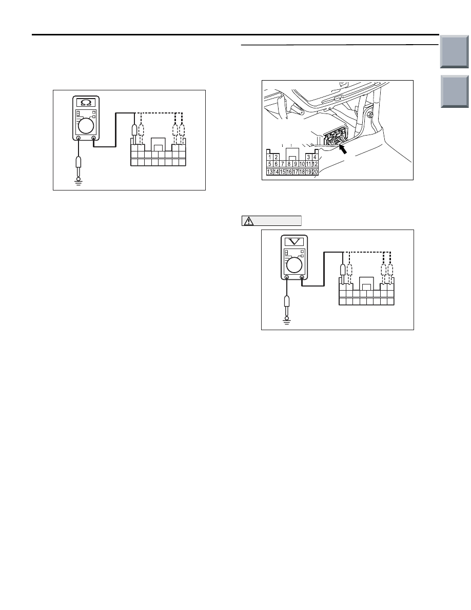
STEP 2. Resistance measurement at the
SRS-ECU connector B-35.
(1) Disconnect the negative battery terminal.
(2) Disconnect SRS-ECU connector B-35.
CAUTION
Do not insert a test probe into the terminal from
its front side directly as the connector contact
pressure may be weakened.
(3) Take the measurements below at harness-side
connector B-35.
Code No.
Trouble causes
1A
• Left front impact sensor or its wiring shorted
1B
• Left front impact sensor or wiring open circuit
1C
• Short to the power supply in the left front impact sensor harness
1D
• Short to body earth in the left front impact sensor harness
2A
• Right front impact sensor or its wiring shorted
2B
• Right front impact sensor or wiring open circuit
2C
• Short to the power supply in the right front impact sensor harness
2D
• Short to body earth in the right front impact sensor harness
AC206285
AF
B-35 (Y)
Connector: B-35
Harness side
connector
(rear view)
AC100338
AC103684
1314151617181920
5 6 7 8 9 101112
1 2
3 4
AC103683 AN
B-35 Harness side
(rear view)
AC100338
1314151617181920
5 6 7 8 9 101112
1 2
3 4
AC103684 AM
B-35 Harness side
(rear view)
Main
Index
Group
TOC
TROUBLESHOOTING
SUPPLEMENTAL RESTRAINT SYSTEM (SRS)
52B-16
• Resistance between terminals 1 and 2 as well
as 3 and 4.
NG: 2
Ω or less (short circuit) or 2 MΩ or
more (open circuit))
• Continuity between terminals 1, 2, 3, 4 and
body earth
OK: Open circuit
Q: Is the check result normal?
YES :
Go to Step 3.
NO :
Go to Step 4.
STEP 3. Voltage measurement at the SRS-ECU
connector B-35.
(1) Disconnect the negative battery terminal.
(2) Disconnect SRS-ECU connector B-35.
(3) Connect the negative battery terminal.
(4) Turn the ignition switch to the "ON" position.
CAUTION
Do not insert a test probe into the terminal from
its front side directly as the connector contact
pressure may be weakened.
(5) Take the measurements below at harness-side
connector B-35.
• Voltage between terminals 1, 2, 3, 4 and body
earth
OK: 0V
Q: Is the check result normal?
YES :
Go to Step 5.
NO :
Go to Step 4.
AC103372
4
1 2
3
5
7
6
8
16
15
14
13
12
11
10
9
20
19
18
17
AK
B-35 Harness side
(rear view)
AC206285
AF
B-35 (Y)
Connector: B-35
Harness side
connector
(rear view)
4
1 2
3
5
7
6
8
16
15
14
13
12
11
10
9
20
19
18
17
AC210613
B-35 Harness side
(rear view)
AD
Main
Index
Group
TOC

TROUBLESHOOTING
SUPPLEMENTAL RESTRAINT SYSTEM (SRS)
52B-17
STEP 4. Check the wiring harness between the
front impact sensor (RH) connector A-24
(terminals 1 and 2) and SRS-ECU connector B-35
(terminals 1 and 2) as well as between front
impact sensor (LH) connector A-13 (terminals 1
and 2) and SRS-ECU connector B-35 (terminals 4
and 3).
NOTE:
Prior to the wiring harness inspection, check interme-
diate connectors B-40, and repair if necessary.
• Check the front impact sensor output line for
open or short circuit.
Q: Is the check result normal?
YES :
Go to Step 5.
NO :
Repair the wiring harness.
STEP 5. Check whether the diagnosis code is
reset.
Check again if the diagnosis code is set.
Q: Is diagnosis code 1A, 1B, 1C, 1D, 2A, 2B, 2C or 2D
set?
YES :
Replace the SRS-ECU (Refer to
).
NO :
An intermittent malfunction is suspected
(Refer to GROUP 00, How to Cope with
Intermittent Malfunction
).
AC313811
Connector: A-13
A-13 (Y)
AK
Harness side
(front view)
2
1
AC313797
Connector: A-24
AG
A-24 (Y)
Harness side
(front view)
2
1
AC206285
AF
B-35 (Y)
Connector: B-35
Harness side
connector
(rear view)
AC313820 AM
Connector: B-40
2
6
1
5
9
3
7 8
4
10
Main
Index
Group
TOC
Нет комментариевНе стесняйтесь поделиться с нами вашим ценным мнением.
Текст