Mitsubishi Colt Ralliart. Manual — part 542

SERVICE PRECAUTIONS
SUPPLEMENTAL RESTRAINT SYSTEM (SRS)
52B-6
SRS-ECU terminal No.
Destination of harness
Remedy
1, 2
Instrument panel wiring harness
→
Front wiring harness
→ Front impact
sensor (RH)
Correct or replace each wiring
harness.
3, 4
Instrument panel wiring harness
→
Front wiring harness
→ Front impact
sensor (LH)
Correct or replace each wiring
harness.
5, 6
Instrument panel wiring harness
→
Seat belt pre-tensioner (LH)
Correct or replace the instrument
panel wiring harness.
7, 8
Instrument panel wiring harness
→
Seat belt pre-tensioner (RH)
Correct or replace the instrument
panel wiring harness.
9, 10
Instrument panel wiring harness
→
Air bag module (Front passenger's
side)
Correct or replace the instrument
panel wiring harness.
11, 12
Instrument panel wiring harness
→
Clock spring
→ Air bag module
(Driver's side)
Correct or replace instrument panel
wiring harness. Replace the clock
spring.
13
Instrument panel wiring harness
→
Junction block (fuse No.37)
Correct or replace the instrument
panel wiring harness.
16
Instrument panel wiring harness
→
Junction block (fuse No.40)
Correct or replace the instrument
panel wiring harness.
18
Instrument panel wiring harness
→
SRS wiring lamp
Correct or replace the Instrument
panel wiring harness.
19
Instrument panel wiring harness
→
Earth
Correct or replace the instrument
panel wiring harness.
20
Instrument panel wiring harness
→
Diagnosis connector
Correct or replace the instrument
panel wiring harness.
21, 22
Instrument panel wiring harness
→
Side-airbag module (LH)
Correct or replace the floor wiring
harness.
23, 24
Instrument panel wiring harness
→
Side-airbag module (RH)
Correct or replace the Instrument
panel wiring harness.
27, 28
Instrument panel wiring harness
→
Curtain air bag wiring harness
→
Curtain air bag module (LH)
Correct or replace each wiring
harness.
29, 30
Instrument panel wiring harness
→
Curtain air bag wiring harness
→
Curtain air bag module (RH)
Correct or replace each wiring
harness.
34, 36
Instrument panel wiring harness
→
Side impact sensor (LH)
Correct or replace the Instrument
panel wiring harness.
40, 42
Instrument panel wiring harness
→
Side impact sensor (RH)
Correct or replace the Instrument
panel wiring harness.
Main
Index
Group
TOC
SERVICE PRECAUTIONS
SUPPLEMENTAL RESTRAINT SYSTEM (SRS)
52B-7
DANGER
After disconnecting the battery cable, wait 60
seconds or more before proceeding with the
following work. In addition, insulate the neg-
ative battery terminal with a tape. The con-
denser inside the SRS-ECU is designed to
retain enough voltage to deploy the air bag
for a short time even after the battery has
been disconnected, so serious injury may
result from unintended air bag deployment if
work is done on the SRS system immediately
after the battery cables are disconnected.
CAUTION
The SRS components and seat belt with pre-ten-
sioner should not be subjected to heat, so
remove the SRS-ECU, driver’s and passenger’s
(front) air bag modules, clock spring, front
impact sensor, side impact sensor, side-airbag
modules, curtain air bag modules and seat belt
pre-tensioner before drying or baking the vehicle
after painting.
• SRS-ECU, air bag modules, clock spring,
impact sensors: 93
°C or more
• Seat belt with pre-tensioner: 90°C or more
CAUTION
Whenever you finish servicing the SRS, always
erase the diagnosis code and check warning
lamp operation to make sure that the system
functions properly.
CAUTION
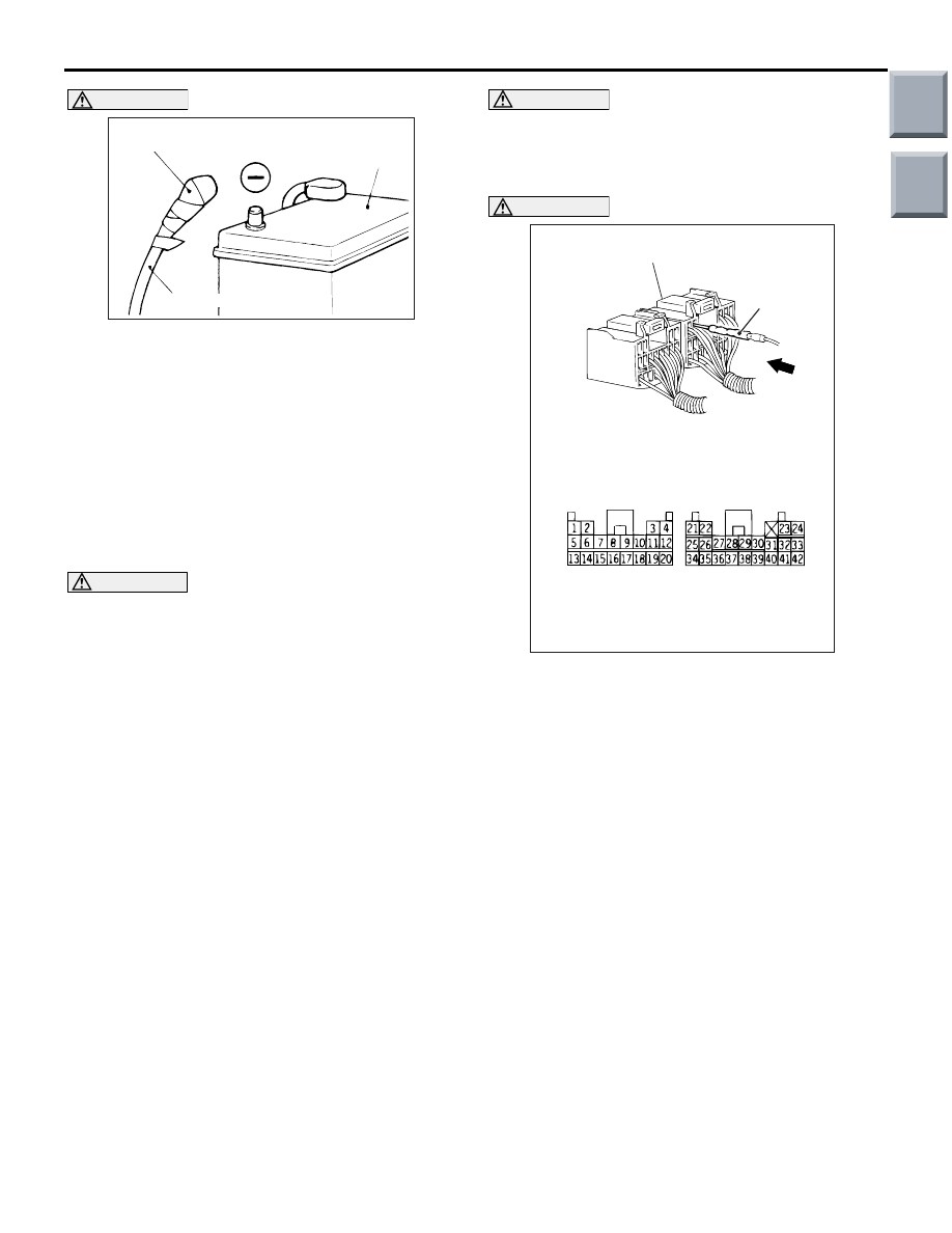
If checks are carried out by using the SRS-ECU
harness connector, observe the following proce-
dures: Insert the special tool extra fine probe
(MB992006) into connector from harness side
(rear side), and connect the tester to this probe. If
any tool than special tool is used, damage to the
harness and other components will result. Never
insert the probe directly to the terminals from the
front of the connector. The terminals are plated
to increase their conductivity, so that if they are
touched directly by the probe, the plating may
break, which will cause drops in reliability.
AC300580AB
Insulating tape
Battery
Battery cable
AC006195
SRS-harness connector
SRS-ECU harness connector
(rear side)
AH
MB992006
Main
Index
Group
TOC

SPECIAL TOOLS
SUPPLEMENTAL RESTRAINT SYSTEM (SRS)
52B-8
SPECIAL TOOLS
M1524000700925
Tool
No.
Name
Application
MB990784
Ornament remover
Removal of cover.
MB990803
Steering wheel puller
Steering wheel disconnection
MB991955
A: MB991824
B: MB991827
C: MB991910
D: MB991911
E: MB991825
F: MB991826
M.U.T.-III sub-assembly
A: Vehicle
Communication
Interface (V.C.I.)
B: M.U.T.-III USB cable
C: M.U.T.-III main
harness A (Vehicles
with CAN
communication system)
D: M.U.T.-III main
harness B (Vehicles
without CAN
communication system)
E: M.U.T.-III measure
adapter
F: M.U.T.-III trigger
harness
CAN bus diagnostics
CAUTION
For vehicles with CAN
communication, use M.U.T.-III
main harness A to send
simulated vehicle speed. If you
connect M.U.T.-III main harness
B instead, the CAN
communication does not
function correctly.
MB991884
Resistor harness (For
Pre-tensioner)
Seat belt with pre-tensioner
circuit check and curtain air bag
MB991865
Dummy resistor
SRS air bag and seat belt with
pre-tensioner circuit check
MB990784
MB990803
MB991910
MB991826
MB991955
MB991911
MB991824
MB991827
MB991825
A
B
C
D
E
F
DO NOT USE
MB991884
MB991865
Main
Index
Group
TOC

TEST EQUIPMENTS
SUPPLEMENTAL RESTRAINT SYSTEM (SRS)
52B-9
TEST EQUIPMENTS
M1524000800386
MB991866
Resistor harness
SRS air bag circuit check
MB686560
SRS air bag adapter
harness
• Deployment of front
passenger's side air bag
module inside the vehicle
• Deployment of front
passenger's side air bag
module outside the vehicle
MB991885
Pre-tensioner adapter
harness
• Deployment of seat belt with
pre-tensioner and curtain air
bag inside the vehicle
• Deployment of seat belt with
pre-tensioner and curtain air
bag outside the vehicle
MB991223
A: MB991219
B: MB991220
C: MB991221
D: MB991222
Harness set
A: Check harness
B: LED harness
C: LED harness
adapter
D: Probe
Checking the continuity and
measuring the voltage at the
SRS-ECU harness connector
MB992006
Extra fine probe
Continuity check and voltage
measurement at harness wire or
connector
Tool
No.
Name
Application
MB991866
MB686560
MB991885
MB991223
A
D
C
B
AZ
DO NOT USE
MB992006
Tool
Name
Application
Digital multi-meter
Checking SRS electrical circuitry (Use
multi-meter for which the maximum test
current is 2 mA or less at minimum range
of resistance measurement
AC300683
Main
Index
Group
TOC
Нет комментариевНе стесняйтесь поделиться с нами вашим ценным мнением.
Текст