Mitsubishi Colt Ralliart. Manual — part 252

FRONT AXLE HUB ASSEMBLY
FRONT AXLE
26-8
<<E>> DRIVESHAFT REMOVAL
CAUTION
• The magnetic encoder collects any metallic
particle easily, because it is magnetized. Make
sure that the magnetic encoder does not col-
lect any metallic particle.
•
AC100128AC
MB990241
MB990767
When the driveshaft is removed, make sure
that it does not contact with the magnetic
encoder to avoid damage.
Use the following special tools to push out the drive-
shaft from the hub.
• Front hub & flange yoke holder (MB990767)
• Axle shaft puller (MB990241)
INSTALLATION SERVICE POINT
>>A<< SELF-LOCKING NUT INSTALLA-
TION
AC207017AB
A
Install the stabilizer rubber and collar as shown in the
figure, and tighten the self-locking nut so that the
protruding length of the stabilizer bar mounting bolt
protruding part meets its standard value (A).
Standard value (A): 19
± 1.5 mm
>>B<<PIN BOOT INSTALLATION
AC209151AB
19 mm deep
socket
Pin boot
Knuckle
Use a 19 mm deep socket to drive a pin boot into the
knuckle.
>>C<< WASHER/DRIVESHAFT NUT
INSTALLATION
CAUTION
• The magnetic encoder collects any metallic
particle easily, because it is magnetized. Make
sure that the magnetic encoder should not
collect any metallic particle. Check that there
is not any trouble prior to reassembling it.
• When the driveshaft is installed, make sure
that it does not contact with the magnetic
encoder to avoid damage.
•
AC102465
Washer
MB990767
AB
Before securely tightening the driveshaft
nuts, make sure there is no load on the wheel
bearings. Otherwise the wheel bearings will
be damaged.
1. Be sure to install the driveshaft washer in the
specified direction.
2. Using special tool front hub & flange yoke holder
(MB990767), tighten the driveshaft nut to the
specified torque.
Tightening torque: 245
± 29 N⋅m
Main
Index
Group
TOC
FRONT AXLE HUB ASSEMBLY
FRONT AXLE
26-9
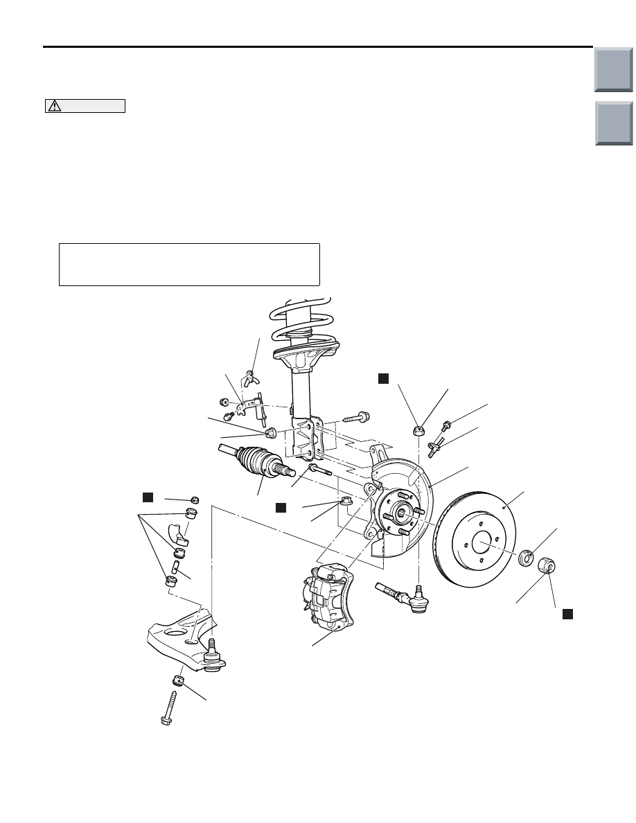
REMOVAL AND INSTALLATION
<VEHICLES WITH 15 INCH-DISC BRAKE>
M1261001701033
CAUTION
• Do not disassemble the front wheel hub assembly.
• The magnetic encoder collects any metallic particle easily, because it is magnetized. Make sure
that the magnetic encoder should not collect any metallic particle. Check that there is not any
trouble prior to reassembling it.
• When the front wheel hub assembly is removed and installed, make sure that the magnetic
encoder does not contact with surrounding parts to avoid damage.
•
Post-installation Operation
Check the dust cover for cracks or damage by pushing it with
your finger.
AC507587
N
245 ± 29 N·m
AC
9
N
66 ± 6 N·m
N
80 ± 10 N·m
25 ± 5 N·m
100 ± 10 N·m
N
5 ± 1 N·m
1
3
2
4
7
5
6
8
10
9
<4A9>
11
12
14
13
15
When the front wheel speed sensor is removed and installed, make sure that its pole piece does
not contact with surrounding parts to avoid damage.
Main
Index
Group
TOC

Removal steps
<<
A
>> >>
B
<< 1.
Driveshaft nut
>>
B
<< 2.
Washer
3.
Front wheel speed sensor
4.
Brake hose bracket
5.
Front wheel speed sensor harness
bracket
<<
B
>>
6.
Caliper assembly
7.
Brake disc
>>
A
<< 8.
Self-locking nut
>>
A
<< 9.
Stabilizer rubber
10. Collar
<<
C
>>
11. Self-locking nut (tie rod end
connection)
<<
C
>>
12. Self-locking nut (lower arm ball
joint connection)
<<
D
>>
13. Driveshaft
14. Nut (hub and knuckle to strut
connection)
15. Hub and knuckle assembly
AC511654
N
245 ± 29 N·m
AE
60 ± 6 N·m
N
80 ± 10 N·m
28 ± 3 N·m
30 ± 5 N·m
N
105 ± 5 N·m
3
2
4
7
5
6
N
1
N
<4G1>
9
8
10
11
12
14
13
15
16
Removal steps
<<
A
>> >>
B
<< 1.
Driveshaft nut
>>
B
<< 2.
Washer
3.
Front wheel speed sensor
4.
Brake hose bracket
5.
Front wheel speed sensor harness
<<
B
>>
6.
Caliper assembly
7.
Brake disc
>>
A
<< 8.
Stabilizer link bush (A)
>>
A
<< 9.
Self-locking nut
10. Stabilizer link assembly
11. Stabilizer link bush (B)
<<
C
>>
12. Self-locking nut (tie rod end
connection)
<<
C
>>
13. Self-locking nut (lower arm ball
joint connection)
<<
D
>>
14. Driveshaft
15. Nut (hub and knuckle to strut
connection)
16. Hub and knuckle assembly
FRONT AXLE HUB ASSEMBLY
FRONT AXLE
26-10
Removal steps (Continued)
Removal steps (Continued)
Main
Index
Group
TOC
FRONT AXLE HUB ASSEMBLY
FRONT AXLE
26-11
REMOVAL SERVICE POINTS
<<A>> DRIVESHAFT NUT REMOVAL
CAUTION
Do not apply pressure to wheel bearing by the
vehicle weight to avoid possible damage when
driveshaft nut is loosened.
AC102462
MB990767
AB
Use special tool front hub & flange yoke holder
(MB990767) to fix the hub and remove the driveshaft
nut.
<<B>> CALIPER ASSEMBLY REMOVAL
Secure the removed caliper assembly with wire, etc.
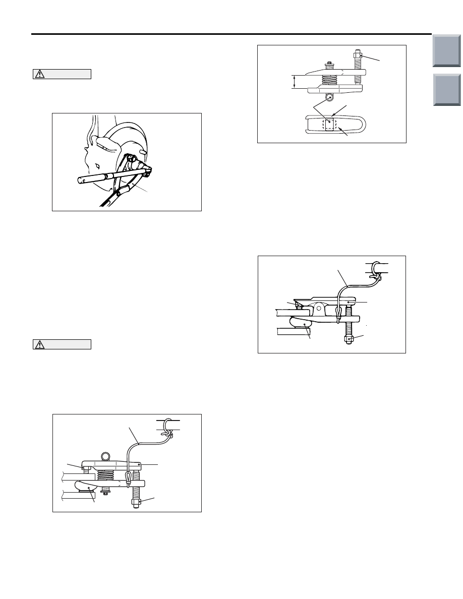
<<C>> SELF-LOCKING NUT (TIE ROD
END CONNECTION)/SELF-LOCKING NUT
(LOWER ARM BALL JOINT
CONNECTION) REMOVAL
CAUTION
• Do not remove the nut from ball joint. Loosen
it and use the special tool to avoid possible
damage to ball joint threads.
• Hang the special tool with cord to prevent it
from falling.
<4A9>
AC208247AJ
Cord
Bolt
MB991897
or
MB992011
Nut
Ball joint
1. Install special tool ball joint remover (MB991897
or MB992011) as shown in the figure.
AC106821
Knob
Parallel
Bolt
Correct
Wrong
AD
2. Turn the bolt and knob as necessary to make the
jaws of special tool parallel, tighten the bolt by
hand and confirm that the jaws are still parallel.
NOTE: When adjusting the jaws in parallel, make
sure the knob is in the position shown in the fig-
ure.
3. Tighten the bolt with a wrench to disconnect the
tie rod end, lower arm ball joint.
<4G1>
AC102599AC
Cord
Bolt
MB991113
Nut
Ball joint
Replace the self-locking nut with a regular nut, and
then install special tool steering linkage puller
(MB991113) as shown in the figure.
Main
Index
Group
TOC
Нет комментариевНе стесняйтесь поделиться с нами вашим ценным мнением.
Текст