Mitsubishi Colt Ralliart. Manual — part 9

ENGINE ASSEMBLY
ENGINE MECHANICAL <4A9>
11A-33
REMOVAL SERVICE POINTS
<<A>> GEARSHIFT AND SELECT CABLE
DISCONNECTION
AC311252AB
Transmission lever
Cable
Section A - A
Lever
Gearshift and select cables
A
A
A
A
1. Disconnect the transmission
assembly-transmission lever from the ends of the
gearshift and select cables.
2. With the bracket installed, remove the gearshift
and select cables from the transmission
assembly.
3. After removing the gearshift and the select cables,
tie them in a place where it will not be a hindrance
when removing and installing the engine and
transmission assembly.
<<B>> FUEL HIGH-PRESSURE HOSE
REMOVAL
AC403077AB
Fuel high-pressure
hose
Stopper
1. Remove the stopper.
AC403078 AB
Fuel high-pressure
hose
Retainer
2. Raise the retainer, and pull out the fuel
high-pressure hose.
NOTE: If the retainer comes off, install it securely
after pulling out the fuel high-pressure hose.
<<C>> A/C COMPRESSOR AND MAGNET
CLUTCH ASSEMBLY REMOVAL
1. With the hose installed, remove the A/C
compressor and magnet clutch assembly from the
cylinder block.
2. Secure the removed A/C compressor and magnet
clutch assembly with cord or rope at a position
where they will not interfere with the removal of
the engine and transmission assembly.
<<D>> CLUTCH RELEASE CYLINDER
ASSEMBLY REMOVAL
1. With the hose installed, remove the clutch release
cylinder assembly from the transmission
assembly.
2. Secure the removed clutch release cylinder
assembly with cord or rope at a position where
they will not interfere with the removal of the
engine and transmission assembly.

ENGINE ASSEMBLY
ENGINE MECHANICAL <4A9>
11A-34
<<E>> TRANSMISSION MOUNTING
INSULATOR CONNECTING BOLT AND
NUT/ENGINE MOUNTING INSULATOR
CONNECTING BOLT AND NUT/ENGINE
MOUNTING INSULATOR REMOVAL
AC403079
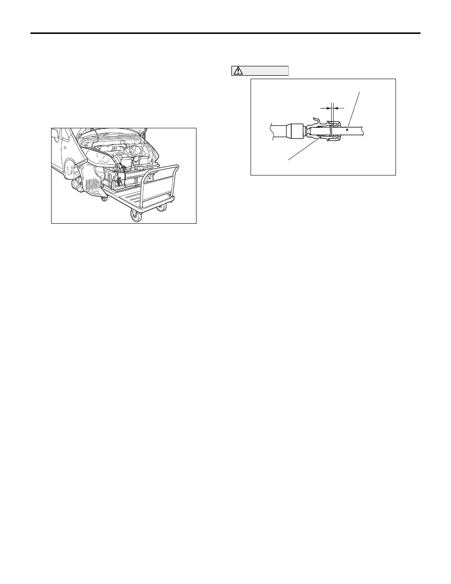
1. Place a cart below the engine and transmission
assembly.
2. Lower the lift to the position where the weight of
the engine and transmission assembly is not
applied to the transmission mounting insulator
and the engine mounting insulator.
3. Remove the self-locking nuts, transmission
mounting insulator mounting bolt and engine
mounting insulator mounting bolts.
CAUTION
Because the engine assembly is installed with
tilted toward the rear side, support the engine
and transmission assembly after removing the
engine mounting insulator.
4. Remove the engine mounting insulator.
<<F>> ENGINE AND TRANSMISSION
ASSEMBLY REMOVAL
1. Confirm that the cable, the hose, and the harness
connector are all disconnected.
CAUTION
Do not bend the fuel high-pressure hose.
2. Raise the body slowly with a lift, and remove the
engine and transmission assembly.
<<G>> TRANSMISSION CONNECTING
BOLT/ENGINE ASSEMBLY REMOVAL
AC311780
AB
MB991454
MB991527
1. Install the chain of special tool engine hanger
balancer (MB991454) and special tool engine
hanger (MB991527), and set the chain block.
2. Remove the transmission assembly connecting
bolts.
CAUTION
When lifting the engine assembly, operate with
care not to lift the transmission assembly.
3. Lift the engine assembly slowly using the chain
block, and remove the transmission assembly
when the engine assembly is lifted a little.
ENGINE ASSEMBLY
ENGINE MECHANICAL <4A9>
11A-35
INSTALLATION SERVICE POINTS
>>A<< ENGINE AND TRANSMISSION
ASSEMBLY/ENGINE MOUNTING INSULA-
TOR/ENGINE MOUNTING INSULATOR
CONNECTING BOLT AND NUT/TRANS-
MISSION MOUNTING INSULATOR CON-
NECTING BOLT AND NUT INSTALLATION
AC403079
1. Place the engine and transmission assembly on
the cart below the lifted vehicle.
2. Lower the lift to the position where the mounting
bolts of the engine mounting insulator and the
transmission mounting insulator, and the
self-locking nuts are installed.
3. Install the engine mounting insulator.
4. Tighten the new self-locking nuts of engine
mounting insulator and transmission mounting
insulator to the specified torque, and tighten the
new mounting bolts of engine mounting insulator
and transmission mounting insulator to the
specified torque.
Tightening torque:
68
± 7 N⋅m <Engine mounting insulator
mounting bolts and nuts>
43
± 4 N⋅m <Transmission mounting insulator
mounting bolt and nuts>
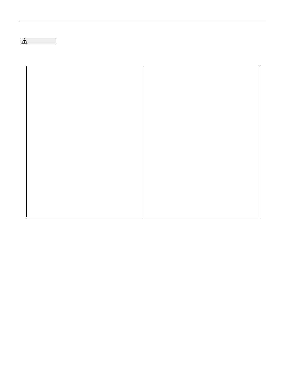
>>B<< FUEL HIGH-PRESSURE HOSE
INSTALLATION
AC208465AE
3 mm
Fuel high-pressure hose
Fuel delivery pipe
CAUTION
• After connecting the fuel high-pressure hose,
check that it has been securely installed by
slightly pulling in the removal direction. At
this time, also check that there is approxi-
mately 3-mm play.
• When applying the engine oil, make sure not
to allow the engine oil to enter the fuel deliv-
ery pipe.
Apply a small amount of the engine oil to the fuel
delivery pipe, and then install the fuel
high-pressure hose.
>>C<< INITIALISATION
When the engine-ECU is removed, initialise the elec-
tronic-controlled throttle valve system according to
the following procedure after installing the
engine-ECU.
Turn the ignition switch from "ON" position to
"LOCK" (OFF) position, and then hold "LOCK"
(OFF) position for approximately 10 seconds or
more.
ENGINE ASSEMBLY
ENGINE MECHANICAL <4A9>
11A-36
REMOVAL AND INSTALLATION <CVT>
M1112001002953
CAUTION
When the engine assembly replacement is performed, use the M.U.T.-III to initialise the learning value
(Refer to GROUP 00, Precautions Before Service
− Initialisation Procedure for Learning Value in MPI
Engine
Pre-removal Operation
• Fuel Line Pressure Reduction [Refer to GROUP 13A,
On-vehicle Service
− Fuel Pump Connector Disconnection
(How to Reduce Pressurized Fuel Lines)
• Front Under Cover Panel Assembly Removal (Refer to
GROUP 51, Front Bumper Assembly and Radiator Grille
).
• Engine Room Side Under Cover Removal
• Engine Coolant Draining (Refer to GROUP 14, On-vehicle
Service
− Engine Coolant Replacement
).
• Engine Oil Draining (Refer to GROUP 12, On-vehicle
Service
− Engine Oil Replacement
).
• Transmission Fluid Draining [Refer to GROUP 23A,
On-vehicle Service
− Transmission Fluid (CVT Fluid)
Replacement
].
• Air Cleaner Assembly Removal (Refer to GROUP15, Air
Cleaner
).
• Battery and Battery Tray Removal
• Alternator and Alternator Brace Removal (Refer to
GROUP 16, Charging System
− Alternator Assembly
• Drive Shaft Removal (Refer to GROUP 26, Drive Shaft
Assembly
• Front Bumper Face Assembly Removal (Refer to GROUP
51, Front Bumper Assembly and Radiator Grille
).
• Radiator Assembly Removal (Refer to GROUP 14, Radia-
).
• Exhaust Manifold Removal (Refer to GROUP15, Exhaust
Manifold
).
Post-installation Operation
• Exhaust Manifold Installation (Refer to GROUP 15,
Exhaust Manifold
• Radiator Assembly Installation (Refer to GROUP 14,
Radiator
).
• Front Bumper Face Assembly Installation (Refer to
GROUP 51, Front Bumper Assembly and Radiator Grille
).
• Drive Shaft Installation (Refer to GROUP 26, Drive Shaft
Assembly
• Alternator and Alternator Brace Installation (Refer to
GROUP 16, Charging System
− Alternator Assembly
• Battery and Battery Tray Installation
• Air Cleaner Assembly Installation (Refer to GROUP 15,
Air Cleaner
).
• Transmission Fluid Refilling [Refer to GROUP 23A,
On-vehicle Service
− Transmission Fluid (CVT Fluid)
Replacement
].
• Engine Oil Refilling (Refer to GROUP12, On-vehicle Serv-
ice
− Engine Oil Replacement
• Engine Coolant Refilling (Refer to GROUP 14 - On-vehi-
cle Service
− Engine Coolant Replacement
).
• Drive Belt Tension Check and Adjustment (Refer to
).
• Engine Room Side Under Cover Installation
• Front Under Cover Panel Assembly Installation (Refer to
GROUP 51, Front Bumper Assembly and Radiator Grille
).
• Fuel Leak Check
Нет комментариевНе стесняйтесь поделиться с нами вашим ценным мнением.
Текст