Mitsubishi Colt Ralliart. Manual — part 755

TROUBLESHOOTING
MULTIPORT FUEL INJECTION (MPI) <4G1>
13B-345
20
Cooling fan
motor (HI)
Fan motor is
driven at high
speed
Ignition switch: ON
Fan motor
rotates at
high speed
Procedure
No. 23
21
Cooling fan
motor (LO)
Fan motor is
driven at low
speed
Ignition switch: ON
Fan motor
rotates at
low speed
Procedure
No. 23
34
Electronic-co
ntrolled
throttle valve
system
Stop the throttle
valve control
servo
Ignition switch: ON
Throttle
valve is
opened
slightly
Code No.
P0638
Item
No.
Inspection
item
Drive content
Inspection conditions
Normal
condition
Inspection
procedure
No.
Reference
page
Main
Index
Group
TOC
TROUBLESHOOTING
MULTIPORT FUEL INJECTION (MPI) <4G1>
13B-346
CHECK AT THE ECU TERMINALS
M1131155100140
TERMINAL VOLTAGE CHECK CHART
1. Disconnect the engine-ECU connector, and
connect check harness special tool MB991987
between the engine-ECU connectors.
2. Measure the voltage between each check
harness connector terminal and check harness
connector earth terminal (No. 75 or No. 76).
3. Connect a needle-nosed wire probe to a voltmeter
probe.
4. Referring to the check sheet, insert the micromini
probe into the check harness connector and
measure the voltage.
NOTE:
.
1. You may find it convenient to pull out the
engine-ECU to make it easier to reach the
connector terminals.
2. The checks can be carried out off the order
given in the chart.
CAUTION
Short-circuiting the positive (+) probe between a
connector terminal and earth could damage the
vehicle wiring, the sensor, engine-ECU or all of
them. Be careful to prevent this!
5. If voltmeter shows any division from standard
value, check the corresponding sensor, actuator
and related electrical wiring, then repair or
replace.
6. After repair or replacement, recheck with the
voltmeter to confirm that the repair has corrected
the problem.
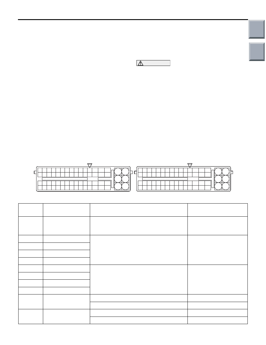
Engine-ECU Connector Terminal Arrangement
AK402726
61
46
31
64
49
19
34
50
51
6665
36
21
35
20
47
48
6362
33
18
32
17
58
43
28
44
45
6059
30
1615
29
14
41
42
5756
27
12
13
26
11
53
38
23
8
39
40
54
55
24
9
L
25
10
37
52
22
7
5
3
1
6
4
2
93
71
72
75
73
76
74
92
77
98
83
95 94
R
96
97
80
78
79
81
82
99
86
84
85
107
122
108
123
109
124
110
125
111
126
112
127
113
128
114
129
115
130
116
131
117
132
118
133
119
134
120
135
121
136
101100
102
103
104
105
106
87
88
919089
A-114
A-08
AB
Special Tool Check Harness (MB991987) Connector Terminal Arrangement
Terminal
No.
Check item
Check condition (Engine condition)
Normal condition
7
Throttle valve control
servo (+)
• Ignition switch: ON
• Accelerator pedal: fully opened → fully
closed
Decreases slightly
(approximately 2 V) from
system voltage
8
No. 1 injector
Engine: While engine is idling after having
warmed up, suddenly depress the
accelerator pedal.
From 9
− 13 V momentarily
drops slightly
9
No. 2 injector
23
No. 3 injector
24
No. 4 injector
10
No. 1 ignition control Engine: 3,000 r/min
0.1
− 2.0 V
25
No. 2 ignition control
40
No. 3 ignition control
55
No. 4 ignition control
12
Camshaft position
sensor
Engine: Cranking
2.0
− 4.8 V
Engine: Idling
3.0
− 4.0 V
13
Crank angle sensor
Engine: Cranking
0.4
− 4.0 V
Engine: Idling
2.0
− 3.0 V
Main
Index
Group
TOC

TROUBLESHOOTING
MULTIPORT FUEL INJECTION (MPI) <4G1>
13B-347
14
Engine coolant
temperature sensor
Ignition switch: ON
When engine coolant
temperature is
−20°C
3.9
− 4.5 V
When engine coolant
temperature is 0
°C
3.2
− 3.8 V
When engine coolant
temperature is 20
°C
2.3
− 2.9 V
When engine coolant
temperature is 40
°C
1.3
− 1.9 V
When engine coolant
temperature is 60
°C
0.7
− 1.3 V
When engine coolant
temperature is 80
°C
0.3
− 0.9 V
15
Throttle position
sensor (main)
• Remove the intake
air hose at the
throttle body
• Disconnect the
connector of the
electronic-controll
ed throttle valve
• Connect only
terminals No. 1,
No. 2, No. 3 and
No. 4 between
disconnected
connectors with
the use of the
special tool:
MB991658
• Ignition switch: ON
(engine stopped
condition)
Fully close the throttle
valve with your finger
0.2
− 0.6 V
Fully open the throttle
valve with your finger
4.3
− 4.7 V
Terminal
No.
Check item
Check condition (Engine condition)
Normal condition
Main
Index
Group
TOC

TROUBLESHOOTING
MULTIPORT FUEL INJECTION (MPI) <4G1>
13B-348
16
Throttle position
sensor (sub)
• Remove the intake
air hose at the
throttle body
• Disconnect the
connector of the
electronic-controll
ed throttle valve
• Connect only
terminals No. 1,
No. 2, No. 3 and
No. 4 between
disconnected
connectors with
the use of the
special tool:
MB991658
• Ignition switch: ON
(engine stopped
condition)
Fully close the throttle
valve with your finger
4.3
− 4.7 V
Fully open the throttle
valve with your finger
0.2
− 0.6 V
22
Throttle valve control
servo (
−)
• Ignition switch: ON
• Accelerator pedal: fully closed → fully
opened
Decreases slightly
(approximately 2 V) from
system voltage
31
Power supply
voltage applied to
throttle position
sensor
Ignition switch: ON
4.9
− 5.1 V
34
Oxygen sensor
(front)
Engine: Running at 2,500 r/min after
warm-up
0.4 or less
⇔ 0.6 − 1.0 V
(Changes repeatedly)
36
Waste gate solenoid
valve
Ignition switch: ON
System voltage
After warming up engine: Idle operation
(when premium gasoline is used)
1 V or less
38
Purge control
solenoid valve
Ignition switch: ON
System voltage
Engine: After warming up, accelerate (4,000
r/min or less)
Voltage decreases
39
Ignition switch
− ST Engine: Cranking
8 V or more
51
Oxygen sensor
(front) heater
Engine: Idling
1 V or less
Engine: 5,000 r/min
System voltage
52
Oil feeder control
valve
Ignition switch: ON
System voltage
Operation at high load
4
− 10 V
57
Fuel pressure
solenoid valve
Ignition switch: ON
System voltage
Engine: Cranking
→ idle operation (within
approximately 2 minutes)
1 V or less
→ System
voltage
64
Alternator G terminal
• Engine: Idling after warm-up
• Radiator fan: Inoperative
• Headlamp switch: OFF → ON
• Stop lamp: OFF → ON
• Rear defogger switch: OFF → ON
Voltage increases by 0.2
−
3.5 V
Terminal
No.
Check item
Check condition (Engine condition)
Normal condition
Main
Index
Group
TOC
Нет комментариевНе стесняйтесь поделиться с нами вашим ценным мнением.
Текст