Mitsubishi Colt Ralliart. Manual — part 113

INTERCOOLER
INTAKE AND EXHAUST
15-8
INTERCOOLER
REMOVAL AND INSTALLATION <4G1>
M1151004200188
AC600078
6.0 ± 1.0 N·m
1
2
3
4
5
6
7
8
9
10
20
13
14
15
N
17
19
16
18
11
6.0 ± 1.0 N·m
24 ± 4 N·m
6.0 ± 1.0 N·m
6.0 ± 1.0 N·m
10 ± 1 N·m
5.0 ± 1.0 N·m
N
20 ± 4 N·m
6.0 ± 1.0 N·m
6.0 ± 1.0 N·m
6.0 ± 1.0 N·m
11 ± 2 N·m
11 ± 2 N·m
AB
12
6.0 ± 1.0 N·m
11 ± 2 N·m
5.4 ± 1.0 N·m
5.4 ± 1.0 N·m
5.4 ± 1.0 N·m
5.4 ± 1.0 N·m
7.5 ± 1.0 N·m
6.0 ± 1.0 N·m
Removal steps
>>
H
<<
1.
Air hose C
>>
G
<< 2.
Air by-pass hose
>>
F
3.
Air by-pass valve
•
Air cleaner assembly (Refer to
)
>>
E
4.
Air pipe B
>>
D
5.
Air hose D
Removal steps (Continued)
Main
Index
Group
TOC
INTERCOOLER
INTAKE AND EXHAUST
15-9
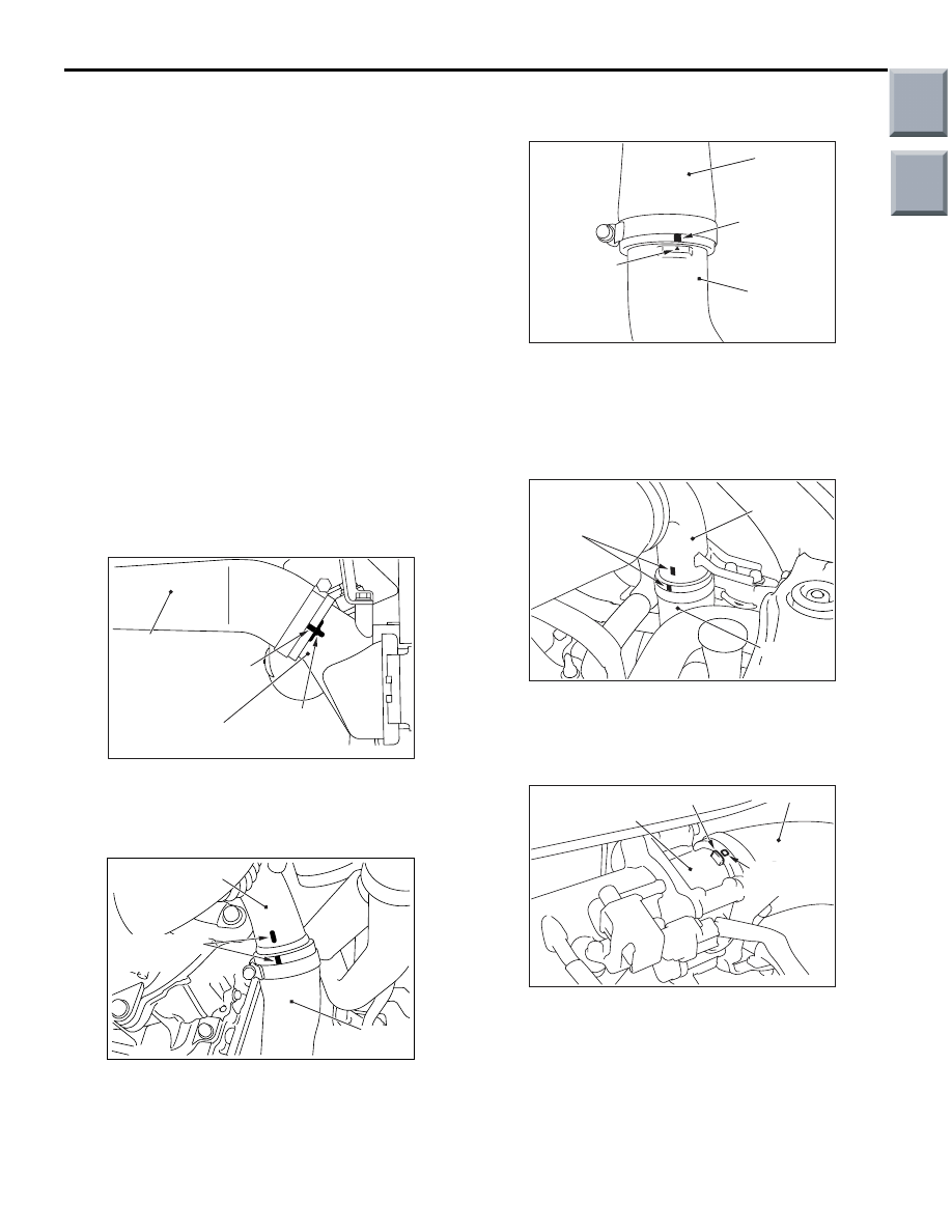
INSTALLATION SERVICE POINTS
>>A<<AIR HOSE A INSTALLATION
AC402293
Intercooler assembly
(inlet side)
Mating mark (green)
Air hose A
Mating mark
AC402293AG
1. Install by aligning the mating mark (green) on air
hose A and the mating mark on the intercooler
assembly (inlet side).
AC402297
AB
Air outlet fitting
Mating mark
(yellow)
Air hose A
2. Install by aligning the mating marks (yellow) on air
hose A and on the air outlet fitting.
>>B<<AIR HOSE B INSTALLATION
AC402295
Air hose B
Mating mark
Mating mark
(yellow)
Intercooler
air pipe
AC402295AC
Install by aligning the mating mark (yellow) on air
hose B and the mating mark on the intercooler air
pipe.
>>C<<AIR PIPE A INSTALLATION
AC600076AB
Mating mark
(white)
Air pipe A
Air hose B
Install by aligning the mating marks (white) on air
pipe A and on air hose B.
>>D<<AIR HOSE D INSTALLATION
AC600077AB
Throttle body
Air hose D
Mating mark
(white)
Projection
Install by aligning the mating mark (white) on air
hose D and the projection on the throttle body.
>>
C
<<
6.
Air pipe A
7.
Bracket
>>
B
<<
8.
Air hose B
>>
A
<<
9.
Air hose A
10. Air outlet fitting
11. Gasket
•
Front bumper assembly (Refer to
GROUP 51
− Front Bumper
Assembly, Radiator Grille
).
•
Side under cover (LH)
12. Intercooler assembly, intercooler
inlet air duct, intercooler air pipe
13. Intercooler assembly
14. Intercooler air pipe
15. O-ring
16. Intercooler inlet air duct
17. Bracket
18. Bracket
19. Intercooler baffle plate
20. Bracket
Removal steps (Continued)
Main
Index
Group
TOC

INTERCOOLER
INTAKE AND EXHAUST
15-10
>>E<<AIR PIPE B INSTALLATION
AC402294
4 mm
(yellow line)
Air hose D
Mating mark
(yellow)
Air pipe B
AC402294AB
1. Align the end of air hose D so that the width of the
yellow line on air pipe B should be 4 mm.
2. Install by aligning the mating marks (yellow) on air
pipe B and on air hose D.
>>F<<AIR BY-PASS VALVE
INSTALLATION
AC600112AB
Air by-pass valve
Engine
air intake hose
Mating mark
(white)
Mating mark
Install by aligning the mating mark (white) on the air
by-pass valve and the mating mark on the engine air
intake hose.
>>G<<AIR BY-PASS HOSE
INSTALLATION
AC402296
AH
Air pipe B
Air by-pass hose
Mating mark
(green)
Mating mark
1. Install by aligning the mating mark (green) on the
air by-pass hose and the mating mark on air pipe
B.
AC402291
Rib
Air by-pass hose
Air by-pass valve
Mating mark (white)
AC402291AB
2. Install by aligning the mating mark (white) on the
air by-pass hose and the centre of the air by-pass
valve rib.
>>H<<AIR HOSE C INSTALLATION
AC402296
AG
Air pipe B
Mating mark
(yellow)
Air hose C
1. Install by aligning the mating marks (yellow) on air
hose C and on air pipe B.
AC402292
AE
Mating mark
(white)
Air pipe A
Mating mark
(green)
Air hose C
2. Install by aligning the mating mark (green) on the
air hose C and the mating mark (white) on the air
pipe A.
Main
Index
Group
TOC
INLET MANIFOLD
INTAKE AND EXHAUST
15-11
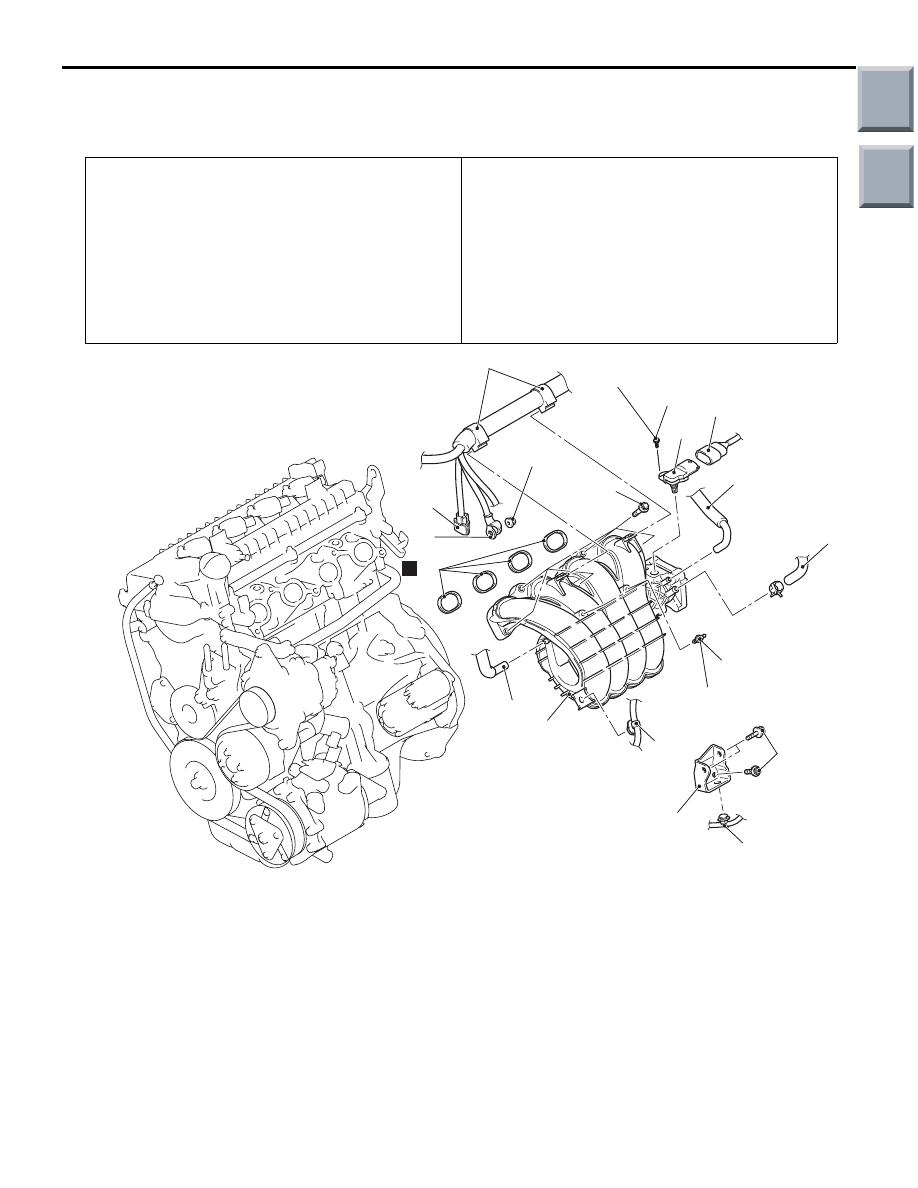
INLET MANIFOLD
REMOVAL AND INSTALLTION <4A9>
M1151003001816
Pre-removal Operation
• Engine Coolant Draining (Refer to GROUP 14, On-vehicle
Service
− Engine Coolant Replacement
).
• Air Cleaner Assembly, Air Intake Duct Removal (Refer to
).
• Throttle Body Removal (Refer to GROUP 13A, Throttle
• Fuel Injector Removal (Refer to Group 13A, Injector
).
• EGR Valve Assembly Removal <CVT> (Refer to GROUP
17, EGR Valve
Post-installation Operation
• EGR Valve Assembly Installation <CVT> (Refer to
GROUP 17, EGR Valve
• Fuel Injector Installation (Refer to GROUP 13A, Injector
).
• Throttle Body Installation (Refer to GROUP 13A, Throttle
Body
• Air Cleaner Assembly, Air Intake Duct Installation (Refer
).
• Engine Coolant Refilling (Refer to GROUP 14, On-vehicle
Service
− Engine Coolant Replacement
).
AC601295AB
14 ± 3 N·m
N
14
1
2
3
4
5
6
7
8
12
13
6.0 ± 0.5 N·m
18 ± 1 N·m
18 ± 1 N·m
9
11 ± 1 N·m
15
10
11
Removal steps
1.
Harness clamp connection
2.
Alternator connector
3.
Alternator terminal
4.
PCV hose connection
5.
Brake booster vacuum hose
connection <M/T>
6.
Purge hose connection <M/T>
7.
Manifold absolute pressure sensor
connector
>>
A
8.
Screw
9.
Manifold absolute pressure sensor
10. Harness clamp connection
11. Harness clamp connection <M/T>
12. Inlet manifold stay <M/T>
13. Inlet manifold
14. Inlet manifold gasket
15. Ball stud
Removal steps (Continued)
Main
Index
Group
TOC
Нет комментариевНе стесняйтесь поделиться с нами вашим ценным мнением.
Текст