Mitsubishi Colt Ralliart. Manual — part 112
ON-VEHICLE SERVICE
INTAKE AND EXHAUST
15-4
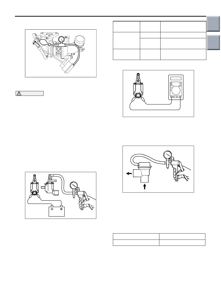
WASTE GATE ACTUATOR CHECK <4G1>
M1151001200297
AK402022
1. Connect a manual pump (pressure-application
type) to nipple.
CAUTION
In order to avoid damage to the diaphragm, do
not apply a pressure of 75 kPa or higher.
2. While gradually applying pressure, check the
pressure that begins to activate (approximately 1
mm stroke) the waste gate actuator rod.
Standard value: Approximately 60 kPa
3. If there is a significant deviation from the standard
value, check the actuator or the waste gate valve:
replace actuator or turbocharger assembly if
necessary.
WASTE GATE SOLENOID VALVE CHECK
<4G1>
M1151001300205
OPERATION CHECK
AK200441
Battery
A
B
AC
1. Connect a hand vacuum pump to the solenoid
valve nipple A.
2. Using a jumper wire, connect between the
solenoid valve terminal and battery terminal.
3. Connecting and disconnecting the jumper wire at
the battery negative terminal to apply a negative
pressure, check tightness.
Jumper wire B nipple
condition
Normal condition
Connected
Opened
Negative pressure leaks.
Closed
Negative pressure is
held.
Disconnected Opened
Negative pressure is
held.
COIL RESISTANCE CHECK
AK200442
Measure the resistance between solenoid valve ter-
minals
Standard value: 29
− 35 Ω (at 20°C)
AIR BY-PASS VALVE CHECK <4G1>
M1151001600165
AK200443
1. Remove the air bypass valve.
2. Connect the hand vacuum pump to the nipple of
the air bypass valve.
3. Apply a negative pressure of approximately 93
kPa, and check that air tightness is maintained.
4. Also check operation of the valve.
Standard value:
Negative pressure
Valve operation
Approximately 53 kPa
It starts opening
INTAKE MANIFOLD VACUUM CHECK
M1151001800266
Refer to GROUP 11A
− On-vehicle Service
. <4A9>
Refer to GROUP 11C
− On-vehicle Service
. <4G1>
Main
Index
Group
TOC

AIR CLEANER
INTAKE AND EXHAUST
15-5
AIR CLEANER
REMOVAL AND INSTALLATION <4A9>
M1151002101177
AC601194AB
9.0 ± 1.0 N·m
1
4
6
3
5
2
7
4.0 ± 1.0 N·m
4.0 ± 1.0 N·m
9.0 ± 1.0 N·m
7
8
10
4.0 ± 1.0 N·m
8
4.0 ± 1.0 N·m
9
<M/T>
<CVT>
Removal steps
1.
Air cleaner intake duct
2.
Air cleaner cover
3.
Air cleaner element
4.
Fuel vapour control hose
5.
Breather hose
6.
Air cleaner body assembly
7.
Clip
8.
Breather hose connection
9.
Engine air intake hose <M/T>
10. Engine air intake hose <CVT>
Removal steps (Continued)
Main
Index
Group
TOC

AIR CLEANER
INTAKE AND EXHAUST
15-6
REMOVAL AND INSTALLATION <4G1>
M1151002101315
AC600110AB
9.0 ± 1.0 N·m
1
4
6
3
5
2
7
4.0 ± 1.0 N·m
4.0 ± 1.0 N·m
4.0 ± 1.0 N·m
9.0 ± 1.0 N·m
8
9
10
11
13
1.8 ± 0.6 N·m
6.0 ± 1.0 N·m
12
Removal steps
1.
Air cleaner intake duct
2.
Air cleaner air flow sensor
connector
3.
Air cleaner air flow sensor, air
cleaner cover assembly
4.
Air cleaner air flow sensor
5.
Air cleaner cover
6.
Air cleaner element
7.
Breather hose
8.
Air cleaner body assembly
9.
Clip
10. Engine air intake hose
11. Breather hose connection
>>
B
12. Air by-pass valve connection
>>
A
13. Engine air intake hose
Removal steps (Continued)
Main
Index
Group
TOC

AIR CLEANER
INTAKE AND EXHAUST
15-7
INSTALLATION SERVICE POINTS
>>A<< ENGINE AIR INTAKE HOSE
INSTALLATION
AC600111AE
Engine
air intake hose
Mating mark
(green)
Nipple
Turbocharger
assembly
Install by aligning the mating mark (green) on the
engine air intake hose with the nipple on the turbo-
charger assembly.
>>B<< AIR BY-PASS VALVE
CONNECTION
AC600112AB
Air by-pass valve
Engine
air intake hose
Mating mark
(white)
Mating mark
Install by aligning the mating mark (white) on the air
by-pass valve and the mating mark on the engine air
intake hose.
Main
Index
Group
TOC
Нет комментариевНе стесняйтесь поделиться с нами вашим ценным мнением.
Текст