Mitsubishi Colt Ralliart. Manual — part 536

ON-VEHICLE SERVICE
HEATER, AIR CONDITIONER AND VENTILATION
55A-52
RELAY CONTINUITY CHECK
M1552008800503
A/C COMPRESSOR RELAY CONTINUITY
CHECK
AC208719
;
AJ
2
4
1
3
3
1
4
2
A/C compressor
CAUTION
Ensure the correct polarity to prevent the dam-
age to a diode.
Battery voltage Tester
connection
Specified
condition
Not applied
3
− 4
Open circuit
• Connect
terminal 1 to
the positive
battery
terminal
• Connect
terminal 2 to
the negative
battery
terminal
3
− 4
Continuity (Less
than 2
Ω)
BLOWER RELAY CONTINUITY CHECK
AC208719
;
AH
2
4
1
3
3
1
4
2
Blower relay
Battery voltage Tester
connection
Specified
condition
Not applied
3
− 4
Open circuit
• Connect
terminal 1 to
the positive
battery
terminal
• Connect
terminal 2 to
the negative
battery
terminal
3
− 4
Continuity (Less
than 2
Ω)
Main
Index
Group
TOC
ON-VEHICLE SERVICE
HEATER, AIR CONDITIONER AND VENTILATION
55A-53
IDLE-UP OPERATION CHECK
M1552001600553
1. Before inspection and adjustment, set vehicle in
the following condition:
• Engine coolant temperature: 80 − 90 °C
• Lamps, electric cooling fan and accessories: Set
to OFF
• Transmission: Neutral ("N" or "P" for vehicles with
A/T)
• Steering wheel: Straightforward
2. Check whether or not the idle speed is the
standard value.
Refer to GROUP 11A, On-vehicle Service
− Basic
Idle Speed Adjustment
.
Standard value: 700
± 50 r/min
3. When the A/C is running after turning the A/C
switch to ON, and the blower switch to the 3(MH)
or 4(HI) position, check to be sure that the idle
speed is at the standard value.
Standard value: 850
± 100 r/min
NOTE: . It is not necessary to make an adjust-
ment, because the idling speed is automatically
adjusted by the ISC system. If, however, a devia-
tion from the standard value occurs for some rea-
son, check the ISC system.
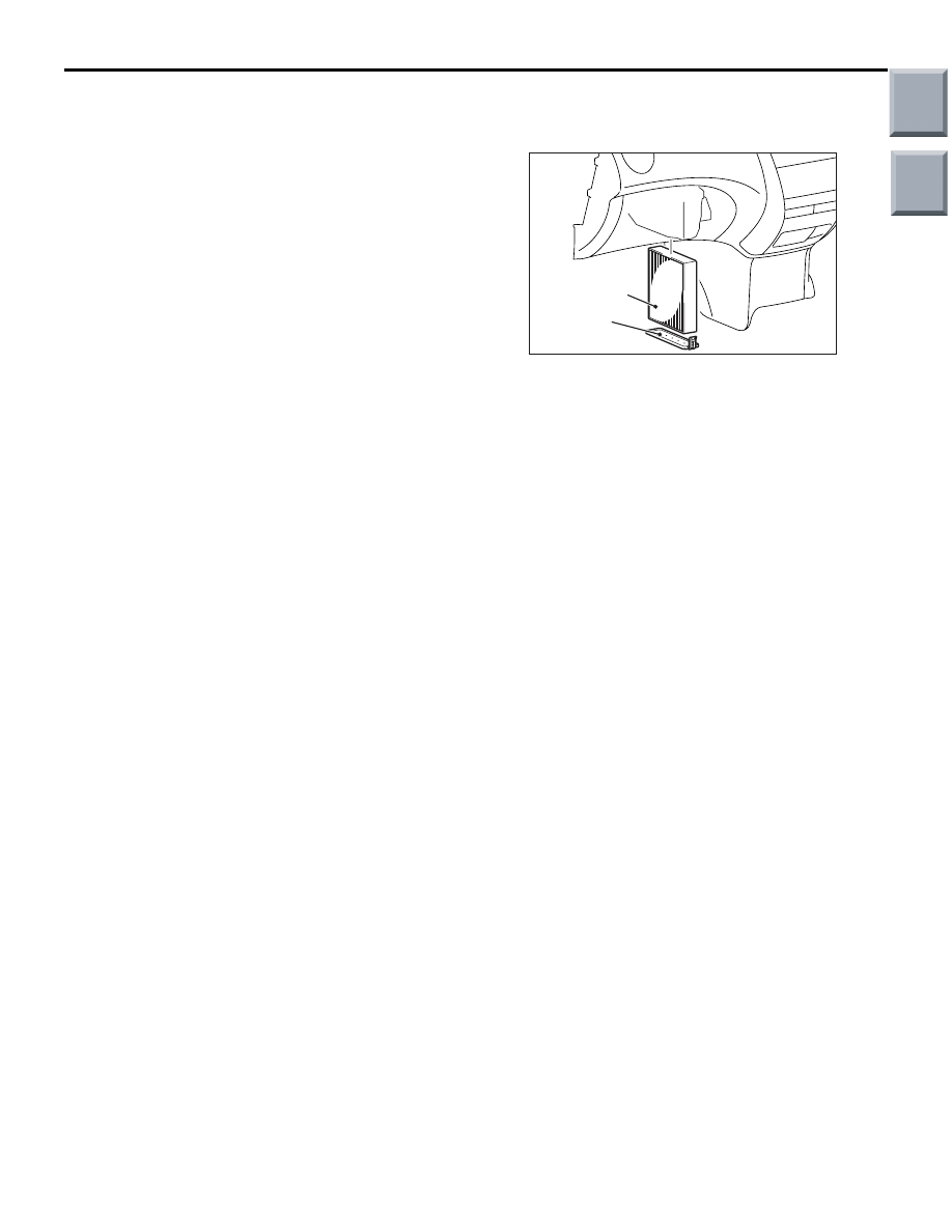
CLEAN AIR FILTER REPLACEMENT
PROCEDURE
M1552020100171
AC314230
Cover
Clean air filter
AB
Remove the cover from the lower side of the front
passenger to extract the clean air filter.
Main
Index
Group
TOC
HEATER CONTROL ASSEMBLY AND A/C SWITCH
HEATER, AIR CONDITIONER AND VENTILATION
55A-54
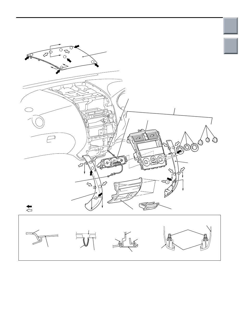
HEATER CONTROL ASSEMBLY AND A/C SWITCH
REMOVAL AND INSTALLATION
M1552002400477
AC206702AB
2
1
2
6
3
8
7
5
C
C
D
D
B
B
A
A
E
E
C
C
NOTE
(1) : Clip position
(2) : Claw position
4
9
11
10
AC208885
Section A – A
Section B – B
Section D – D
AB
Section C – C
Section E – E
Instrument panel
Upper centre
panel
Upper centre
panel
Clip
Instrument
panel
Claw
Claw
Instrument
panel
Console
panel
Console
panel
Clip
Console panel
Instrument
panel
Removal steps
1.
Upper centre panel
2.
Console panel
3.
Ashtray
4.
Lower centre panel
>>
B
<<
5.
Mode selection damper control
cable connection
>>
A
6.
Air mixing damper control cable
connection
7.
Heater control panel assembly
8.
Knob
9.
Heater control assembly
Removal steps (Continued)
Main
Index
Group
TOC

HEATER CONTROL ASSEMBLY AND A/C SWITCH
HEATER, AIR CONDITIONER AND VENTILATION
55A-55
INSTALLATION SERVICE POINT
>>A<< AIR MIXING DAMPER CONTROL
CABLE CONNECTION
AC206694
MAX HOT
MAX COOL
AB
Air mixing
damper lever
1. Turn the temperature control knob of heater
control assembly to the HOT side fully.
2. Turn the air mix damper lever of heater unit to the
MAX HOT position (Turn the damper lever to the
right until it stops.) and then install the cable.
3. Install the cable to the clip and fix it while aligning
the case.
>>B<< MODE SELECTION DAMPER
CONTROL CABLE CONNECTION
AC206695
Mode selection damper
control cable connection
AB
FACE position
DEF position
1. Set the air outlet changeover knob of the heater
control assembly to DEF position.
2. Turn the air outlet changeover damper lever of
heater unit to the DEF position (Turn the damper
lever to the left until it stops.) and then install the
cable.
3. Install the cable to the clip and fix it while aligning
the case.
INSPECTION
M1552002500184
BLOWER SWITCH CONTINUITY CHECK
AC206701AB
5
2
4
1
6
3
Switch
position
Tester connection
Specified
condition
OFF
1
− 2, 2 − 4, 2 − 5, 2 - 6 Open circuit
1
1
− 2
Continuity
(Less than
2
Ω)
2
2
− 4
3
2
− 5
4
2
− 6
10. Mode label
11. Heater control panel
Removal steps (Continued)
Main
Index
Group
TOC
Нет комментариевНе стесняйтесь поделиться с нами вашим ценным мнением.
Текст