Mitsubishi Colt Ralliart. Manual — part 534

TROUBLESHOOTING
HEATER, AIR CONDITIONER AND VENTILATION
55A-44
SERVICE DATA REFERENCE TABLE
M1554005100266
Item No.
Check items
Check contents
02
Ambient temperature sensor Ignition switch: ON
Ambient temperature is the
same as M.U.T.-III displayed
temperature
03
Air thermo sensor
Ignition switch: ON
Evaporator outlet temperature
is the same as M.U.T.-III
displayed temperature
04
A/C pressure sensor
Ignition switch: ON
According with the chart for
simple inspection of the A/C
pressure sensor (Refer to
GROUP 55, On-vehicle
Service
).
05
Water temperature sensor
Ignition switch: ON
The coolant temperature is
the same as M.U.T.-III
displayed temperature
07
Set temperature
Ignition switch: ON
Displays the set temperature
08
Set temperature (control
part set value)
Ignition switch: ON
Display the control part set
temperature
15
Outside/Inside air selection
damper
Ignition switch: ON
Display the outside/inside air
selection damper position
20
Blower motor
Ignition switch: ON
Display the rotation speed of
blower motor
21
Blower motor (Target)
Ignition switch: ON
Display the target rotation
speed of blower motor
30
A/C switch
Ignition switch: ON
Display the A/C switch status
31
A/C switch (control part set
value)
Ignition switch: ON
A/C switch status
35
Rear window defogger
switch (control part set
value)
Ignition switch: ON
Display the rear window
defogger switch status
36
Blower switch
Ignition switch: ON
Display the blower switch
status
37
Outside/Inside air selection
switch
Ignition switch: ON
Display the outside/inside air
selection switch status
40
Abnormal low pressure
judgement
Ignition switch: ON
Displays the abnormal low
pressure judgement
41
Refrigerant leaks judgement Ignition switch: ON
Display the refrigerant leaks
judgement
42
DEF position flag
Ignition switch: ON
Display the DEF position flag
43
Forcible DEF position flag
Ignition switch: ON
Display the forcible DEF
position flag
44
Forcible DEF DRY flag
Ignition switch: ON
Display the forcible DEF DRY
flag
Main
Index
Group
TOC

TROUBLESHOOTING
HEATER, AIR CONDITIONER AND VENTILATION
55A-45
ACTUATOR TEST TABLE
M1554005200241
Item No.
Check items
Drive content
01
Blower motor: OFF
Stop
02
Blower motor: 8 speed
Middle speed
03
Blower motor: 16 speed
High speed
30
Outside/Inside air selection damper control
motor
Moved to recirculation-side
31
Moved to outside air-side
40
Rear defogger switch
OFF
41
ON
09*
Condenser fan
Stop
0B*
OPERATION
50*
Idle-up requirement
OFF
51*
Low-load
52*
High-load
NOTE: *: Drive at the engine operation
Main
Index
Group
TOC
TROUBLESHOOTING
HEATER, AIR CONDITIONER AND VENTILATION
55A-46
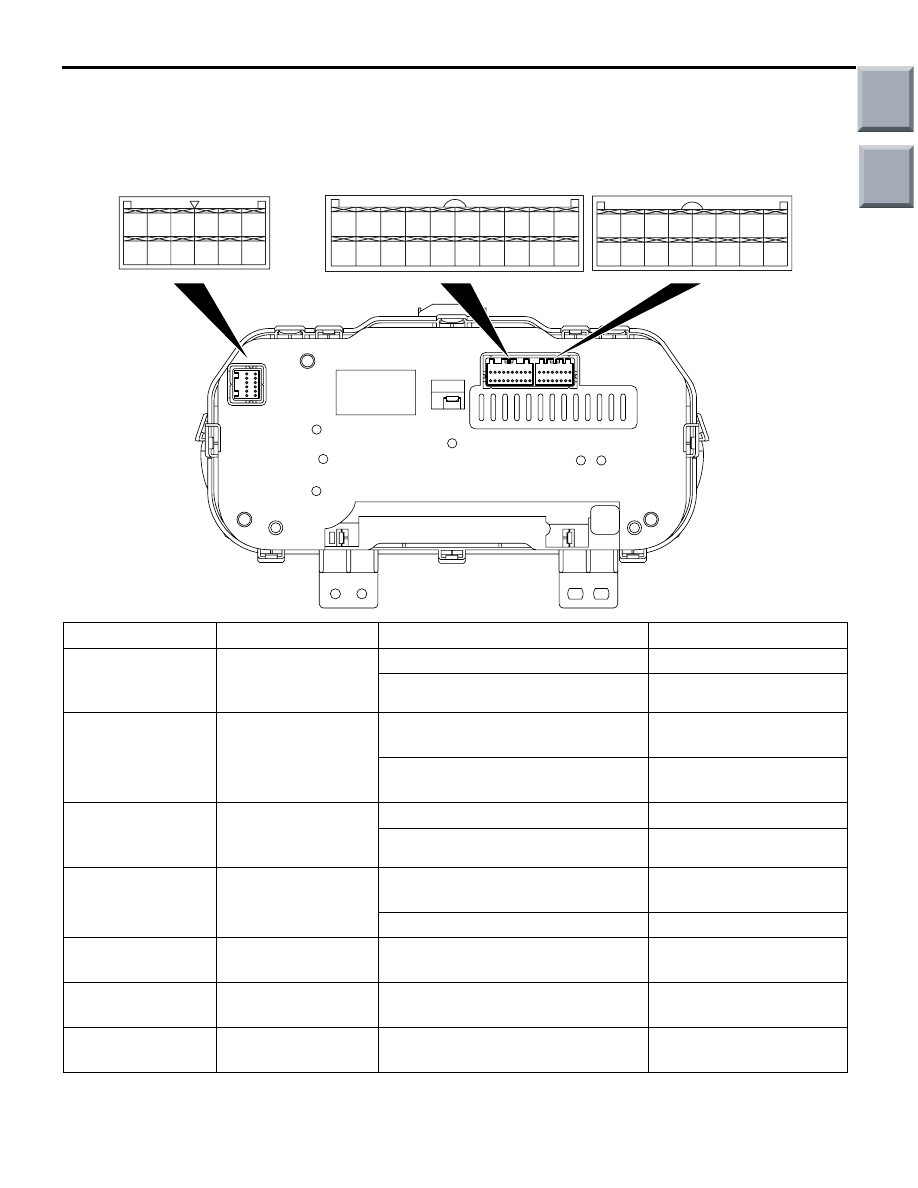
CHECK AT COMBINATION METER
(METER AND A/C-ECU) TERMINALS
M1552010300787
AC206265
AB
35
34
252627
32
31
24
2223
33
29
21
30
36
28
52
49 50 51
44
43
45 46
48
47
41 42
20
19
18
17
7
6
15
14
4
3
1112 13
5
1
9 10
2
16
8
Terminal No.
Check items
Check conditions
Normal conditions
4
Communication with
heater control (Rear
defogger switch)
Rear window defogger relay: ON
System voltage
Rear window defogger relay: OFF
0 V
5
Communication with
heater control
(Outside/Inside air
selection switch)
Outside/Inside air selection switch:
ON
System voltage
Outside/Inside air selection switch:
OFF
0 V
6
Communication with
heater control (A/C
switch)
A/C switch: ON
12 V
A/C switch: OFF
0 V
7
Blower switch
IG2: ON
Blower switch: ON
System voltage
Blower switch: OFF
0 V
8
Input from the A/C
pressure sensor
Refer to
Refer to
9
Air thermo sensor
Sensor probe temperature 25
°C
(1.5k
Ω)
2.2 V
10
Ambient
temperature sensor
Sensor probe temperature 25
°C
(1.5k
Ω)
2.2 V
Main
Index
Group
TOC

TROUBLESHOOTING
HEATER, AIR CONDITIONER AND VENTILATION
55A-47
11
Heater control panel
illumination
(Outside/Inside air
selection switch)
When setting the air recirculation
position
12 V
When setting the fresh air position
0 V
12
Heater control panel
illumination (Rear
defogger switch)
Defogger switch: ON
12 V
Defogger switch: OFF
0 V
13
Rear defogger relay IG2: ON
System voltage
15
Sensor earth
Always
0 V
16
Outside/Inside air
selection damper
control motor
When the damper is moved to the
inside air recirculation position
0 V
When the damper is moved to the
fresh air position
System voltage
17
Outside/Inside air
selection damper
control motor
When the damper is moved to the
inside air recirculation position
System voltage
When the damper is moved to the
fresh air position
0 V
18
Heater control panel
illumination (A/C
switch)
A/C switch: ON
12 V
A/C switch: OFF
0 V
29
Heater control power
supply
IG2: ON
12 V
30
A/C pressure sensor
power supply
IG2: ON
5 V
31
Ignition switch (IG1)
power supply
IG1: ON
System voltage
32
Ignition switch (IG2)
power supply
IG2: ON
System voltage
33
Battery power supply Always
System voltage
34
A/C pressure sensor
earth
Always
0 V
35
Heater control earth Always
0 V
Terminal No.
Check items
Check conditions
Normal conditions
Main
Index
Group
TOC
Нет комментариевНе стесняйтесь поделиться с нами вашим ценным мнением.
Текст