Mitsubishi Colt Ralliart. Manual — part 5

CAMSHAFT
ENGINE MECHANICAL <4A9>
11A-17
CAMSHAFT
REMOVAL AND INSTALLATION
M1112007800111
AC507705
2
16
12
11
10
8
6
14
5
4
3
AB
N
7.6 ± 0.6 N·m
9.0 ± 1.0 N·m
8.4 ± 0.6 N·m
88 ± 10 N·m
8.4 ± 0.6 N·m
5
8.4 ± 0.6 N·m
13
65 ± 5 N·m
20 ± 1 N·m
15
15
15
11 ± 1 N·m
11 ± 1 N·m
17
19
18
7.6 ± 0.6 N·m
N
22
21
44 ± 5 N·m
20
15
7
N
1
9
49 ± 9 N·m
Apply engine oil to all
moving parts before
installation.
(Engine oil)
(Engine oil)
Camshaft removal steps
•
Air cleaner assembly removal
(Refer to GROUP 15, Air Cleaner
).
1.
Engine cover
•
Ignition coil (Refer to GROUP 16,
Ignition System
− Ignition Coil
<<
A
>>
•
Cowl top panel (Refer to GROUP
42, Loose Panel
).
Camshaft removal steps

CAMSHAFT
ENGINE MECHANICAL <4A9>
11A-18
REMOVAL SERVICE POINTS
<<A>> COWL TOP PANEL REMOVAL
CAUTION
After removing the cowl top panel, perform oper-
ation with care not to damage the windshield.
AC311000
AC403071AB
Windshield
Protection
tape
After removing the cowl top panel, attach a protec-
tion tape for the windshield on the lower area of the
windshield.
<<B>> CYLINDER HEAD COVER
ASSEMBLY REMOVAL
AC405036
AB
7
3
6
1
9
5
2
10
4
8
Engine front
Loosen the cylinder head cover assembly mounting
bolts in the order of the numbers shown in the illus-
tration.
<<C>> TIMING CHAIN TENSIONER
REMOVAL
CAUTION
Never turn the crankshaft anti-clockwise.
AC311261
AC
V.V.T. sprocket
assembly
Camshaft sprocket
Timing mark
(2 concave parts)
Timing mark
(Slot portion)
V.V.T. sprocket assembly
Timing mark
(Slot portion)
1. Turn the crankshaft clockwise, and align the
timing mark of the camshaft sprocket (2 conceive
areas in front of the camshaft sprocket) and that
of the V.V.T. sprocket assembly (the groove of
V.V.T. sprocket assembly side face). Then set
No.1 cylinder to the TDC.
2.
Breather hose connection
3.
PCV hose connection
4.
Fuel injector connector
5.
Control harness clamp connection
6.
Engine oil level gauge and guide
assembly
7.
O-ring
<<
B
>>
>>
F
8.
Cylinder head cover assembly
9.
Tensioner pulley
•
Valve clearance adjustment (Refer
to
).
>>
E
10. Timing chain tensioner cover
<<
C
>>
>>
D
<<
11. Timing chain tensioner
<<
D
>>
>>
C
<<
12. Camshaft sprocket
Camshaft removal steps
<<
D
>>
>>
C
13. V.V.T. sprocket assembly
<<
D
>>
>>
C
14. Front camshaft bearing cap
<<
D
>>
>>
C
15. Camshaft bearing cap
<<
D
>>
>>
C
16. Camshaft
Oil control valve removal steps
17. Oil control valve connector
<<
E
>>
B
18. Oil control valve
>>
B
19. O-ring
20. Oil control valve filter bolt
21. Gasket
<<
E
>>
A
22. Oil control valve filter
Camshaft removal steps
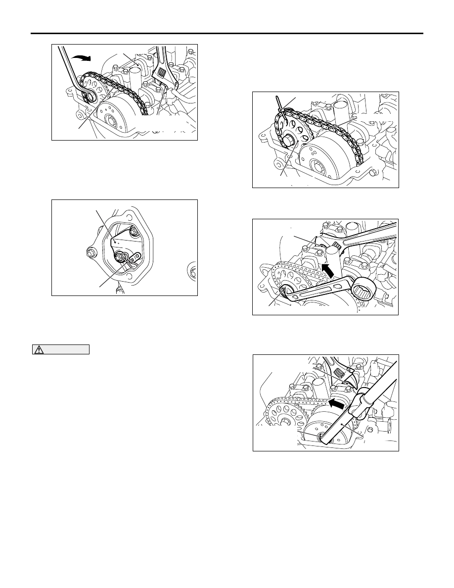
AC311262
AC
Timing chain
Hexagon part of
the inlet camshaft
Exhaust camshaft
CAMSHAFT
ENGINE MECHANICAL <4A9>
11A-19
2. While holding the inlet camshaft hexagonal area
with a wrench or a similar tool, slightly turn the
exhaust camshaft clockwise to tighten the timing
chain at the timing chain tensioner side and
shorten the plunger of the timing chain tensioner.
AC311263
AB
Timing chain tensioner
Pin
3. With the plunger of the tensioner shortened, insert
a pin or a similar tool (3 mm or less in diameter) to
the hole shown in the illustration of the timing
chain tensioner.
CAUTION
Do not turn the crankshaft after removing the tim-
ing chain tensioner.
4. Loosen the timing chain tensioner mounting bolts,
and remove the timing chain tensioner from the
timing chain case hole.
<<D>> CAMSHAFT SPROCKET/ V.V.T.
SPROCKET ASSEMBLY/FRONT
CAMSHAFT BEARING CAP/CAMSHAFT
BEARING CAP/CAMSHAFT REMOVAL
AC312249
AB
Timing chain
Cable band
Camshaft sprocket
1. Fix the camshaft sprocket and the timing chain
using a cable band or a similar tool.
AC311264
AB
Hexagon part of
the exhaust camshaft
Camshaft sprocket mounting bolt
2. While holding the exhaust camshaft hexagonal
area with a wrench or a similar tool, loosen the
camshaft sprocket mounting bolt.
AC311265
AC
Hexagon part of
the inlet camshaft
V.V.T. sprocket
assembly
mounting bolt
MB991992
3. While holding the inlet camshaft hexagonal area
using a wrench or a similar tool, use special tool
torque wrench adapter (MB991992) to loosen the
V.V.T. sprocket assembly mounting bolt.

AC403719
AD
1
1
1
2
2
2
3
3
3
4
4
5
5
6
6
7
7
8
8
Engine front
Front camshaft
bearing cap
Camshaft bearing cap
Camshaft bearing cap
CAMSHAFT
ENGINE MECHANICAL <4A9>
11A-20
4. Loosen the front camshaft bearing cap mounting
bolts, and then loosen each camshaft bearing cap
mounting bolts in the order shown. Remove the
front camshaft bearing cap and each camshaft
bearing cap.
CAUTION
Do not turn the crankshaft after removing the
camshaft sprocket assembly with the timing
chain.
AC312250
AB
Exhaust
camshaft
Camshaft sprocket
mounting bolt
Camshaft sprocket and
timing chain assembly
5. Slightly raise the exhaust camshaft with the
camshaft sprocket and timing chain assembly
from the cylinder head, remove the camshaft
sprocket mounting bolt, and disconnect the
camshaft sprocket and timing chain assembly
from the exhaust camshaft.
6. In the same way as Step 5, disconnect the V.V.T.
sprocket assembly and timing chain assembly
from the inlet camshaft.
CAUTION
After disconnecting the camshaft sprocket and
the V.V.T. sprocket assembly (with the timing
chain for each) from the camshaft, do not dislo-
cate the camshaft sprocket, the V.V.T. sprocket
assembly, and the timing chain.
7. After removal, place the camshaft sprocket and
timing chain assembly, and the V.V.T. sprocket
assembly and timing chain assembly on the
timing chain case assembly
<<E>> OIL CONTROL VALVE/OIL
CONTROL VALVE FILTER REMOVAL
CAUTION
After removing the oil control valve and the oil
control valve filter, be careful that no dust or
other objects enter the oil passage in the cylinder
head.
Нет комментариевНе стесняйтесь поделиться с нами вашим ценным мнением.
Текст