Mitsubishi Colt Ralliart. Manual — part 98

TROUBLESHOOTING
MULTIPORT FUEL INJECTION (MPI) <4A9>
13A-346
NOTE: *:The average voltage is shown when an
analog voltmeter is used (because the average volt-
age might not be shown stably when digital voltmeter
is used).
81
A/C relay
• Engine: Idle speed
• A/C switch: OFF → ON (A/C compressor is
operating)
System voltage
→ 1 V or
less
82
Backup power
supply
Ignition switch: "LOCK" (OFF)
System voltage
83
Accelerator pedal
position sensor
(main)
Ignition switch: ON
Release the
accelerator pedal
0.8
− 1.2 V
Depress the
accelerator pedal fully
4.0 V or more
85
Power supply
voltage applied to
accelerator pedal
position sensor
(main)
Ignition switch: ON
4.9
− 5.1 V
86
Power supply
voltage applied to
accelerator pedal
position sensor (sub)
Ignition switch: ON
4.9
− 5.1 V
88
Accelerator pedal
position sensor (sub)
Ignition switch: ON
Release the
accelerator pedal
0.3
− 0.7 V
Depress the
accelerator pedal fully
2 V or more
95
Fan control relay
Fan inactive state
System voltage
Fan low-speed rotation state
1 V or less
97
Oxygen sensor
(rear)
Engine: Running at 2,500 r/min after warmed
up
0.2
− 0.8 V (After several
seconds have elapsed)
107
Engine control relay Ignition switch: "LOCK" (OFF)
System voltage
Ignition switch: ON
1 V or less
110
Fuel pump relay
Ignition switch: ON
System voltage
Engine: Idle speed
1 V or less
122
Ignition switch
− IG
Ignition switch: ON
System voltage
123
Throttle valve control
servo relay
Ignition switch: "LOCK" (OFF)
0
− 0.1 V
Ignition switch: ON
1 V or less
128
Stop lamp switch
Release the brake pedal
1 V or less
Depress the brake pedal
System voltage
Terminal
No.
Check item
Check condition (Engine condition)
Normal condition
Main
Index
Group
TOC
TROUBLESHOOTING
MULTIPORT FUEL INJECTION (MPI) <4A9>
13A-347
CHECK CHART FOR RESISTANCE AND
CONTINUITY BETWEEN TERMINALS
1. Turn the ignition switch to "LOCK" (OFF) position.
2. Disconnect the engine-ECU connector or
engine-CVT-ECU connector.
3. Measure the resistance and check for continuity
between the terminals of the engine-ECU <M/T>
or engine-CVT-ECU <CVT> harness-side
connector while referring to the check chart.
NOTE:
.
1. When measuring resistance and checking
continuity, a harness for checking contact pin
pressure should be used instead of inserting a
test probe.
2. Checking need not be carried out in the order
given in the chart.
CAUTION
If the terminals that should be checked are mis-
taken, or if connector terminals are not correctly
shorted to earth, damage may be caused to the
vehicle wiring, sensors, engine-ECU <M/T> or
engine-CVT-ECU <CVT> and/or ohmmeter. Be
careful to prevent this!
4. If the ohmmeter shows any deviation from the
standard value, check the corresponding sensor,
actuator and related electrical wiring, and the
repair or replace.
5. After repair or replacement, recheck with the
ohmmeter to confirm that the repair or
replacement has corrected the problem.
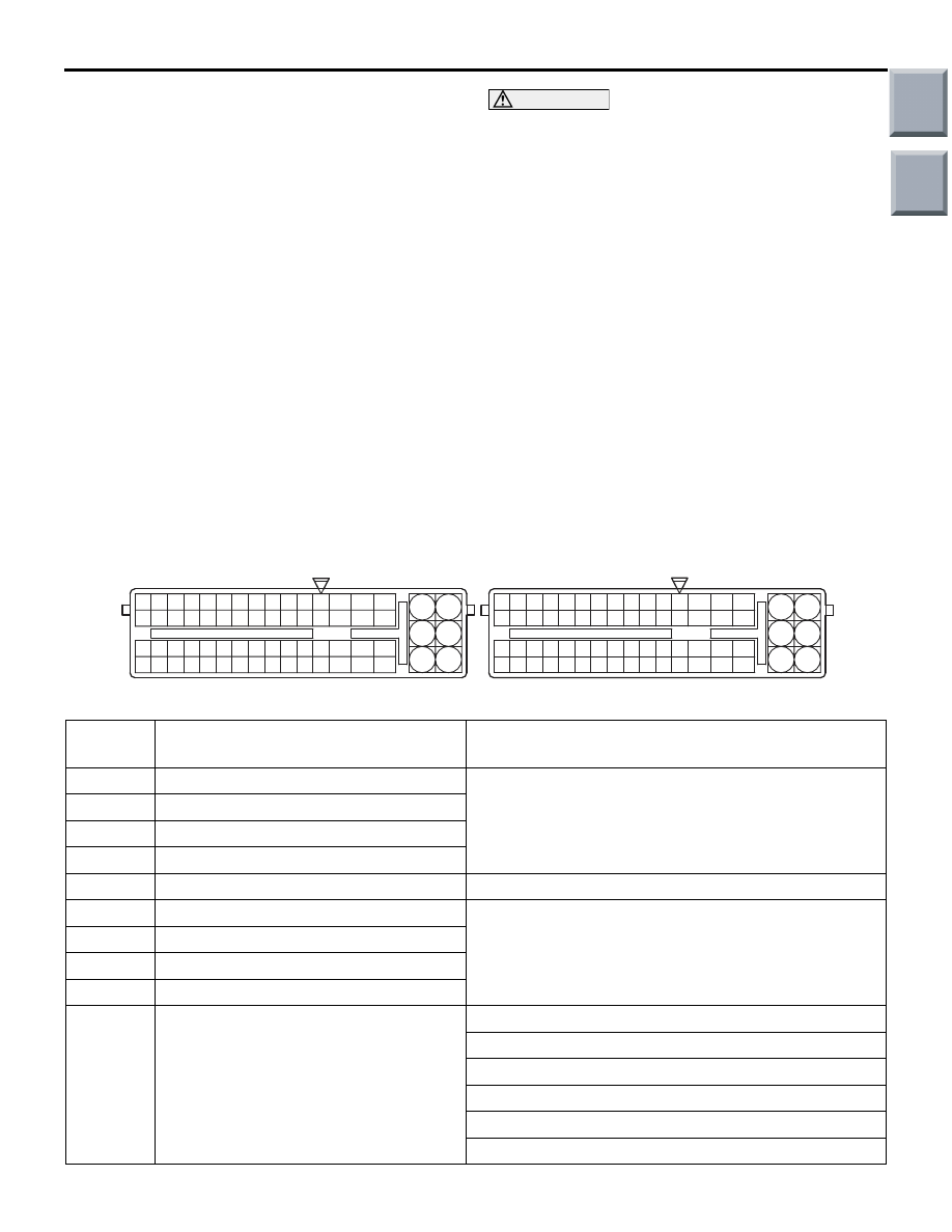
Engine-ECU <M/T> or Engine-CVT-ECU <CVT> Harness Side Connector Terminal
Arrangement
AK402726
61
46
31
64
49
19
34
50
51
6665
36
21
35
20
47
48
6362
33
18
32
17
58
43
28
44
45
6059
30
1615
29
14
41
42
5756
27
12
13
26
11
53
38
23
8
39
40
54
55
24
9
L
25
10
37
52
22
7
5
3
1
6
4
2
93
71
72
75
73
76
74
92
77
98
83
95 94
R
96
97
80
78
79
81
82
99
86
84
85
107
122
108
123
109
124
110
125
111
126
112
127
113
128
114
129
115
130
116
131
117
132
118
133
119
134
120
135
121
136
101100
102
103
104
105
106
87
88
919089
A-114
A-08
AG
Engine-ECU <M/T> or Engine-CVT-ECU <CVT>
Harness Side Connector
Terminal
No.
Inspection item
Normal condition (Check condition)
5
− 92
EGR valve (A) <CVT>
20
− 24 Ω (at 20°C)
6
− 92
EGR valve (B) <CVT>
53
− 92
EGR valve (C) <CVT>
54
− 92
EGR valve (D) <CVT>
7
− 22
Throttle valve control servo
0.3
− 100 Ω (at 20°C)
8
− 92
No. 1 injector
14
− 15 Ω (at 20°C)
9
− 92
No. 2 injector
23
− 92
No. 3 injector
24
− 92
No. 4 injector
14
− 29
Engine coolant temperature sensor
14
− 17 kΩ (When coolant temperature is −20°C)
5.1
− 6.5 kΩ (When coolant temperature is 0°C)
2.1
− 2.7 kΩ (When coolant temperature is 20°C)
0.9
− 1.3 kΩ (When coolant temperature is 40°C)
0.48
− 0.68 kΩ (When coolant temperature is 60°C)
0.26
− 0.36 kΩ (When coolant temperature is 80°C)
Main
Index
Group
TOC

TROUBLESHOOTING
MULTIPORT FUEL INJECTION (MPI) <4A9>
13A-348
INSPECTION PROCEDURE USING
OSCILLOSCOPE
M1131154501728
The output signals of the sensors and the conditions
of the actuation signals of the actuators can be
inspected visually by observing the waveforms on
the oscilloscope.
CAMSHAFT POSITION SENSOR AND
CRANK ANGLE SENSOR
Measurement Method
1. Disconnect the camshaft position sensor
connector and connect the special tool Test
harness (MB991709) in between (All terminals
should be connected).
2. Connect the oscilloscope special pattern pickup to
camshaft position sensor terminal No. 2.
3. Disconnect the crank angle sensor intermediate
connector and connect the special tool Test
harness (MB991658) in between.
4. Connect the oscilloscope special patterns pickup
to crank angle sensor terminal No. 2.
Alternate Method (Test harness not
available)
1. Disconnect the engine-ECU connector or
engine-CVT-ECU connector and connect the
special tool Power plant ECU check harness
(MB991987) in between.
2. Connect the oscilloscope special patterns pickup
to engine-ECU <M/T> or engine-CVT-ECU
<CVT> terminal No. 12 (When checking the
camshaft position sensor signal wave pattern).
3. Connect the oscilloscope special patterns pickup
to engine-ECU <M/T> or engine-CVT-ECU
<CVT> terminal No. 13 (When checking the crank
angle sensor signal wave pattern).
33
− 56
Intake air temperature sensor
13
− 17 kΩ (When intake air temperature is −20°C)
5.3
− 6.7 kΩ (When intake air temperature is 0°C)
2.3
− 3.0 kΩ (When intake air temperature is 20°C)
1.0
− 1.5 kΩ (When intake air temperature is 40°C)
0.56
− 0.76 kΩ (When intake air temperature is 60°C)
0.30
− 0.42 kΩ (When intake air temperature is 80°C)
38
− 92
Purge control solenoid valve
30
− 34 Ω (at 20°C)
51
− 92
Oxygen sensor heater (front)
5
− 30 Ω (at 20°C)
52
− 92
Oil feeder control valve
6.9
− 7.9 Ω (at 20°C)
75
− Body
earth
Engine-ECU <M/T> or
engine-CVT-ECU <CVT> earth
Continuity (2
Ω or less)
76
− Body
earth
93
− Body
earth
108
−
Body
earth
79
− 92
Oxygen sensor heater (rear)
5
− 30 Ω (at 20°C)
Terminal
No.
Inspection item
Normal condition (Check condition)
1 2 3
3
2
1
AK304513
Special patterns
pick-up
Oscilloscope
AC
Camshaft position
sensor connector
Crank angle sensor
intermediate
connector
Main
Index
Group
TOC

TROUBLESHOOTING
MULTIPORT FUEL INJECTION (MPI) <4A9>
13A-349
Standard Wave Pattern
Observation condition
Wave Pattern Observation Points
Check that cycle time T becomes shorter when the
engine speed increases.
Examples of Abnormal Wave Patterns
•
Example 1
Cause of problem
Sensor interface malfunction
Wave pattern characteristics
Rectangular wave pattern is output even when
the engine is not started.
•
Example 2
Cause of problem
Loose timing belt
Abnormality in sensor disk
Wave pattern characteristics
Wave pattern is displaced to the left or right.
Function
Special patterns
Pattern height
Low
Pattern selector
Display
Engine speed
Idle
AK204111AC
(V)
5
0
5
0
No. 1TDC
No. 3TDC
No. 4TDC
No. 2TDC
time
Standard wave pattern
Crank angle
sensor output
wave pattern
Camshaft position
sensor output
wave pattern
2 engine revolutions
(1 camshaft revolution)
TDC: Top dead centre
AK304525
AK203244
Main
Index
Group
TOC
Нет комментариевНе стесняйтесь поделиться с нами вашим ценным мнением.
Текст