Mitsubishi Colt Ralliart. Manual — part 132
EMISSION CONTROL
ENGINE AND EMISSION CONTROL
17-19
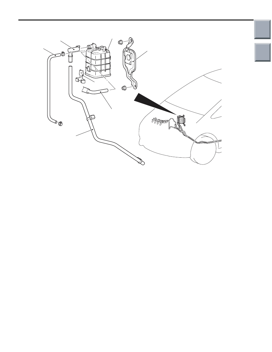
<From Jun. 2006 models>
AC600433AB
1
2
3
4
5
7
6
Removal steps
1.
Purge hose connection
2.
Vapour hose
3.
Vent connector
4.
Vapour hose
5.
Canister
6.
Clamp
7.
Canister bracket
EXHAUST GAS RECIRCULATION (EGR) VALVE
GENERAL INFORMATION (EGR SYSTEM)
<4A9-CVT>
M1173005200822
The exhaust gas recirculation (EGR) system lowers
the nitrogen oxide (NOx) emission level.
When the air/fuel mixture combustion temperature is
high, a large quantity of nitrogen oxides (NOx) is
generated in the combustion chamber.
Therefore, this system recirculates part of emission
gas from the exhaust port of the cylinder head to the
combustion chamber through the inlet manifold to
decrease the air/fuel mixture combustion tempera-
ture, resulting in reduction of NOx.
The EGR flow rate is controlled by the EGR valve so
as not to decrease the driveability.
OPERATION
The EGR valve is being closed and does not recircu-
late exhaust gases under one of the following condi-
tions.
Otherwise, the EGR valve is opened and recirculates
exhaust gases.
• The engine coolant temperature is low.
• The engine is at idle.
• The throttle valve is widely opened.
Removal steps (Continued)
Main
Index
Group
TOC

EMISSION CONTROL
ENGINE AND EMISSION CONTROL
17-20
SYSTEM DIAGRAM
AK306111
EGR valve
(stepper motor)
Engine
control
relay
Battery
Engine-CVT-ECU
Manifold absolute
pressure sensor
Engine coolant
temperature sensor
Crank angle sensor
Throttle position sensor
AC
COMPONENT LOCATION (EGR SYSTEM)
<4A9-CVT>
M1173007600503
AK402709AB
EGR valve
(stepper motor)
EGR VALVE (STEPPER MOTOR) CHECK
<4A9-CVT>
M1173050200349
CHECKING THE OPERATION SOUND
AK402709AB
EGR valve
(stepper motor)
1. Check that the operation sound of the stepper
motor can be heard from the EGR valve when the
ignition switch is turned ON (without starting the
engine).
2. If the operation sound cannot be heard, inspect
the drive circuit of the stepper motor.
NOTE: If the circuit is normal, either the stepper
motor or the engine-CVT-ECU may have failed.
Main
Index
Group
TOC
EMISSION CONTROL
ENGINE AND EMISSION CONTROL
17-21
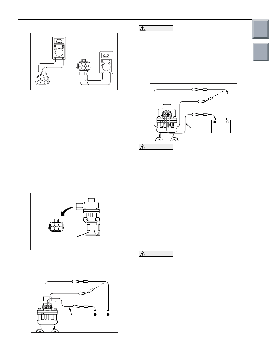
CHECKING THE COIL RESISTANCE
AK200805
1 2 3
4 5 6
1 2 3
4 5 6
AC
1. Remove the EGR valve.
2. Measure the resistance between terminal No. 2
and either terminal No. 1 or terminal No. 3 of the
connector at the EGR valve.
Standard value: 20
− 24 Ω (at 20°C)
3. Measure the resistance between terminal No. 5
and either terminal No. 6 or terminal No. 4 of the
connector at the EGR valve.
Standard value: 20
− 24 Ω (at 20°C)
4. Using a new gasket, install the EGR valve by
tightening its mounting bolts to the specified
torque.
Tightening Torque: 18
± 1 N⋅m
OPERATION CHECK
AK202365
1 2 3
4 5 6
AD
EGR valve
1. Remove the EGR valve.
2. Attach a test wiring harness (special tool
MB991658) to the connector at the EGR valve.
AK402710
Battery
MB991658
AB
CAUTION
Connecting battery voltage to the EGR valve for a
long term could damage the coil.
3. Connect the positive (+) terminal of the battery to
terminal No. 2.
4. Connect terminals No. 1 and No. 3 to the negative
(-) terminal of the battery, in order to test whether
the stepper motor vibrates (with a slight shudder),
indicating that the stepper motor is operating.
AK402711
Battery
MB991658
AB
CAUTION
Connecting battery voltage to the EGR valve for a
long term could damage the coil.
5. Connect the positive (+) terminal of the battery to
terminal No. 5.
6. Connect terminals No. 4 and No. 6 to the negative
(-) terminal of the battery, in order to test whether
the stepper motor vibrates (with a slight shudder),
indicating that the stepper motor is operating.
7. If a vibration can be felt during the test, the
stepper motor is normal.
8. Using a new gasket, install the EGR valve by
tightening its mounting bolts to the specified
torque.
Tightening torque: 18
± 1 N⋅m
CLEANING THE EGR VALVE
CAUTION
Do not use a solvent or detergent, which could
enter the motor and cause it to malfunction.
1. Remove the EGR valve and check that the EGR
valve is not stuck or clogged with carbon deposits.
Use a wire brush to clean the valve if necessary.
2. Using a new gasket, install the EGR valve by
tightening its mounting bolts to the specified
torque.
Tightening torque: 18
± 1 N⋅m
Main
Index
Group
TOC

EMISSION CONTROL
ENGINE AND EMISSION CONTROL
17-22
REMOVAL AND INSTALLATION <4A9-CVT>
M1173010500692
Pre-removal and Post-installation Operation
• Air Cleaner Assembly, Air Cleaner Duct Removal and
Installation (Refer to GROUP 15, Air Cleaner
).
• Throttle Body Assembly Removal and Installation (Refer
to GROUP13A, Throttle Body
).
• Starter assembly Removal and Installation (Refer to
GROUP16, Starter
).
AC601296AB
N
9
18 ± 1 N·m
10
16
17
12
15
N
14
13
N
18
N
19
18 ± 1 N·m
18 ± 1 N·m
7.6 ± 0.6 N·m
1
2
3
4
5
6
7
8
11
18 ± 1 N·m
Removal steps
1.
Harness clamp connection
2.
Oxygen sensor connector
3.
Brake booster vacuum hose
connection
4.
Brake booster vacuum pipe and
brake booster vacuum hose
assembly
5.
Harness clamp connection
6.
Purge solenoid valve connector
7.
Purge hose connection
8.
Engine hanger, purge solenoid
valve and purge solenoid assembly
9.
Harness clamp connection
10. EGR stay
11. EGR valve connector
12. EGR valve and EGR valve pipe
assembly
13. EGR valve gasket
14. EGR equip pipe
>>
C
15. EGR valve gasket
16. EGR valve
17. EGR valve pipe
>>
B
18. EGR pipe gasket B
>>
A
19. EGR pipe gasket A
Removal steps (Continued)
Main
Index
Group
TOC
Нет комментариевНе стесняйтесь поделиться с нами вашим ценным мнением.
Текст