Mitsubishi Colt Ralliart. Manual — part 324

SYMPTOM PROCEDURES
SMART WIRING SYSTEM (SWS) NOT USING SWS MONITOR
54B-40
SYMPTOM PROCEDURES
Inspection Procedure A-1: Communication with the M.U.T.-III is not possible.
CAUTION
Whenever the ECU is replaced, ensure that the
power supply circuit, the earth circuit and the
communication circuit are normal.
COMMENTS ON TROUBLE SYMPTOM
It is suspected that the power supply circuit to the
ETACS-ECU is defective, or the wiring harness
between the diagnosis connector and the
ETACS-ECU or their connector(s) is damaged.
NOTE: If the wiring harness between the
ETACS-ECU and body earth is defective, also check
B-134 ETACS-ECU connector terminal No.2, and
repair if necessary.
POSSIBLE CAUSES
• Malfunction of the ETACS-ECU
• Damaged harness wires and connectors
DIAGNOSTIC PROCEDURE
Step 1. Check that the M.U.T.-III communicates
with the other systems.
Use the M.U.T.-III to confirm that it communicates
with the engine-ECU.
Q: Is the check result normal?
YES :
Go to Step 2.
NO :
Diagnose the system, which cannot
communicate with the M.U.T.-III.
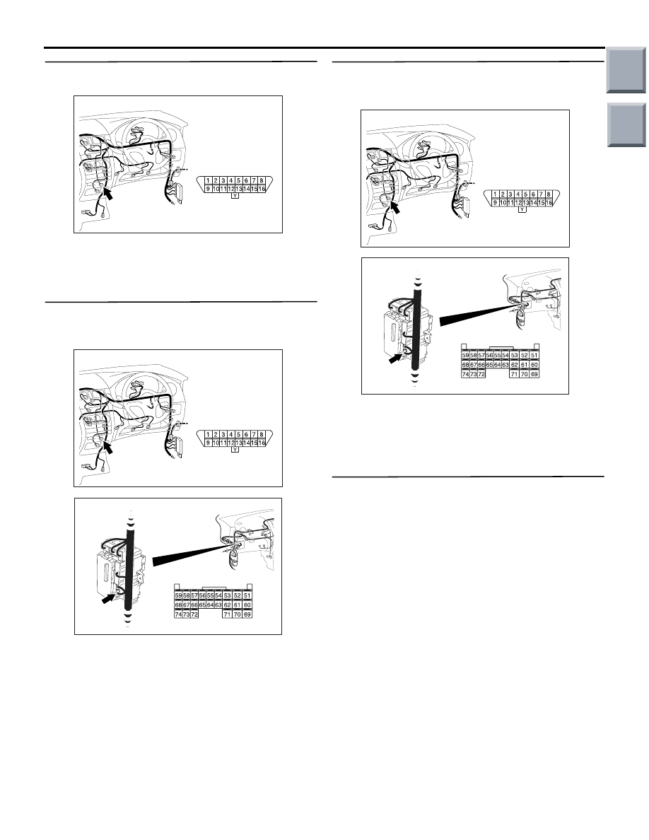
ETACS-
ECU
J/B SIDE
DIAGNOSIS
CONNECTOR
FRONT SIDE
Wire colour code
B : Black LG : Light green G : Green L : Blue
W : White Y : Yellow SB : Sky blue BR : Brown
O : Orange GR : Gray R : Red P : Pink V : Violet
MUT-III Communication and ETACS-ECS Circuit
Main
Index
Group
TOC

SYMPTOM PROCEDURES
SMART WIRING SYSTEM (SWS) NOT USING SWS MONITOR
54B-41
Step 2. Check that the M.U.T.-III can communicate
with the system.
When the ignition switch is turned ON, check if the
M.U.T.-III can communicate with the system.
Q: Is the check result normal?
YES :
Refer to Inspection Procedure A-2 "When
the ignition switch is at the LOCK (OFF)
position, the functions do not work normally.
Check the battery power supply circuit to
the ETACS-ECU
."
NO :
Go to Step 3.
Step 3. Connector check: B-133 ETACS-ECU
connector
Q: Is the check result normal?
YES :
Go to Step 4.
NO :
Repair the defective connector.
Step 4. Resistance measurement at the B-133
ETACS-ECU connector.
(1) Disconnect the connector, and measure at the
junction block side.
(2) Resistance between B-133 ETACS-ECU
connector terminal No.70 and body earth
OK: Continuity exists (2
Ω or less)
Q: Is the check result normal?
YES :
Go to Step 6.
NO :
Go to Step 5.
Step 5. Check the wiring harness between B-133
ETACS-ECU connector terminal No.70 and body
earth.
• Check the earth wires for open circuit.
Q: Is the check result normal?
YES :
The trouble can be an intermittent
malfunction (Refer to GROUP 00
− How to
use Troubleshooting/inspection Service
Points
− How to Cope with Intermittent
).
NO :
Repair the wiring harness.
AC313826 AB
Connector: B-133
Harness side
B-133 (GR)
AC313826 AB
Connector: B-133
Harness side
B-133 (GR)
AC310506
51
52
53
54
55
56
57
58
59
60
61
62
63
64
65
66
67
68
69
70
71
72
73
74
AC310506EL
Connector B-133
(Harness side)
AC313826 AB
Connector: B-133
Harness side
B-133 (GR)
Main
Index
Group
TOC
SYMPTOM PROCEDURES
SMART WIRING SYSTEM (SWS) NOT USING SWS MONITOR
54B-42
Step 6. Connector check: B-32 diagnosis
connector
Q: Is the check result normal?
YES :
Go to Step 7.
NO :
Repair the defective connector.
Step 7. Check the wiring harness from B-133
ETACS-ECU connector terminal Nos. 52 and 69 to
B-32 diagnosis connector terminal Nos. 9 and 1.
• Check the communication lines for open circuit.
Q: Is the check result normal?
YES :
Go to Step 8.
NO :
Repair the wiring harness.
Step 8. Check the wiring harness from B-133
ETACS-ECU connector terminal No.54 to B-32
diagnosis connector terminal No.3.
• Check the communication lines for open circuit.
Q: Is the check result normal?
YES :
Go to Step 9.
NO :
Repair the wiring harness.
Step 9. Retest the system.
Check whether the communication with the M.U.T.-III
is possible.
Q: Is the check result normal?
YES :
The trouble can be an intermittent
malfunction (Refer to GROUP 00
− How to
use Troubleshooting/inspection Service
Points
− How to Cope with Intermittent
).
NO :
Replace the ETACS-ECU.
AC401055
AF
Connector: B-32
B-32 (B)
Harness side
AC401055
AF
Connector: B-32
B-32 (B)
Harness side
AC313826 AB
Connector: B-133
Harness side
B-133 (GR)
AC401055
AF
Connector: B-32
B-32 (B)
Harness side
AC313826 AB
Connector: B-133
Harness side
B-133 (GR)
Main
Index
Group
TOC
SYMPTOM PROCEDURES
SMART WIRING SYSTEM (SWS) NOT USING SWS MONITOR
54B-43
Inspection Procedure A-2: When the ignition switch is at the LOCK (OFF) position, the functions do
not work normally. Check the battery power supply circuit to the ETACS-ECU.
CAUTION
Whenever the ECU is replaced, ensure that the
power supply circuit and the earth circuit are nor-
mal.
COMMENTS ON TROUBLE SYMPTOM
If this circuit is defective and the ignition switch is at
the LOCK (OFF) position, the ETACS-ECU does not
work. In this case, the functions below will be sus-
pended.
• Lamp reminder function
• Keyless entry system
• Ignition key cylinder illumination lamp
However, when the ignition switch is at the ON posi-
tion, the functions below will work.
• Reading diagnosis code and checking input sig-
nal by M.U.T.-III.
• Central door locking
• Headlamp and tail lamp
• Hazard warning lamp
• Interior lamps
POSSIBLE CAUSES
• Malfunction of the ETACS-ECU
• Damaged harness wires and connectors
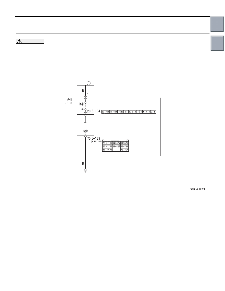
ETACS-ECS Power Supply Circuit
1
FUSIBLE
LINK
ETACS-
ECU
J/B SIDE
Wire colour code
B : Black LG : Light green G : Green L : Blue W : White Y : Yellow SB : Sky blue
BR : Brown O : Orange GR : Grey R : Red P : Pink V : Violet PU : Purple
Main
Index
Group
TOC
Нет комментариевНе стесняйтесь поделиться с нами вашим ценным мнением.
Текст