Acura RLX HYBRID (2020 year). Manual in english — page 35
562
Han
d
lin
g the U
n
expected
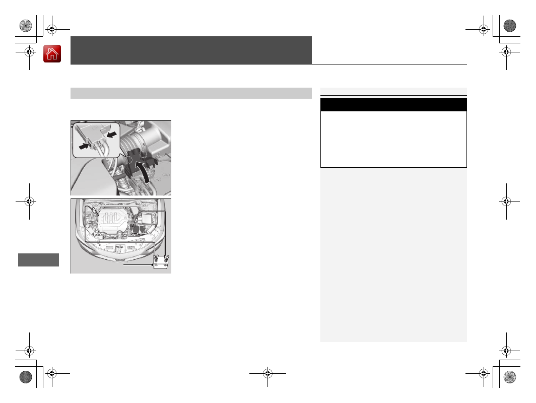
Jump Starting
Turn off the power to electric devices, such as audio and lights. Turn off the power
system, then open the hood.
1.
Open the fuse box cover on your vehicle’s
12-volt battery positive
+
terminal.
2.
Connect the first jumper cable to your
vehicle’s 12-volt battery
+
terminal.
3.
Connect the other end of the first jumper
cable to the booster battery
+
terminal.
u
If you use a booster battery, only use a
12-volt booster battery.
u
When using an automotive battery
charger, select a charging voltage lower
than 15-volts. Check the charger manual
for the proper setting.
4.
Connect the second jumper cable to the
booster battery
-
terminal.
■
Jump Starting Procedure
1
Securely attach the jumper cable clips so that they do
not come off when the engine vibrates. Also be
careful not to tangle the jumper cables or allow the
cable ends to touch each other while attaching or
detaching the jumper cables.
Battery performance degrades in cold conditions and
may prevent the engine from starting.
3
WARNING
A 12-volt battery can explode if you do not
follow the correct procedure, seriously
injuring anyone nearby.
Keep all sparks, open flames, and smoking
materials away from the 12-volt battery.
Booster Battery
-------------------------------------------------------------------------------------------------------------------------------------------------------------
563
uu
Jump Starting
u
Continued
Han
d
lin
g the U
n
expected
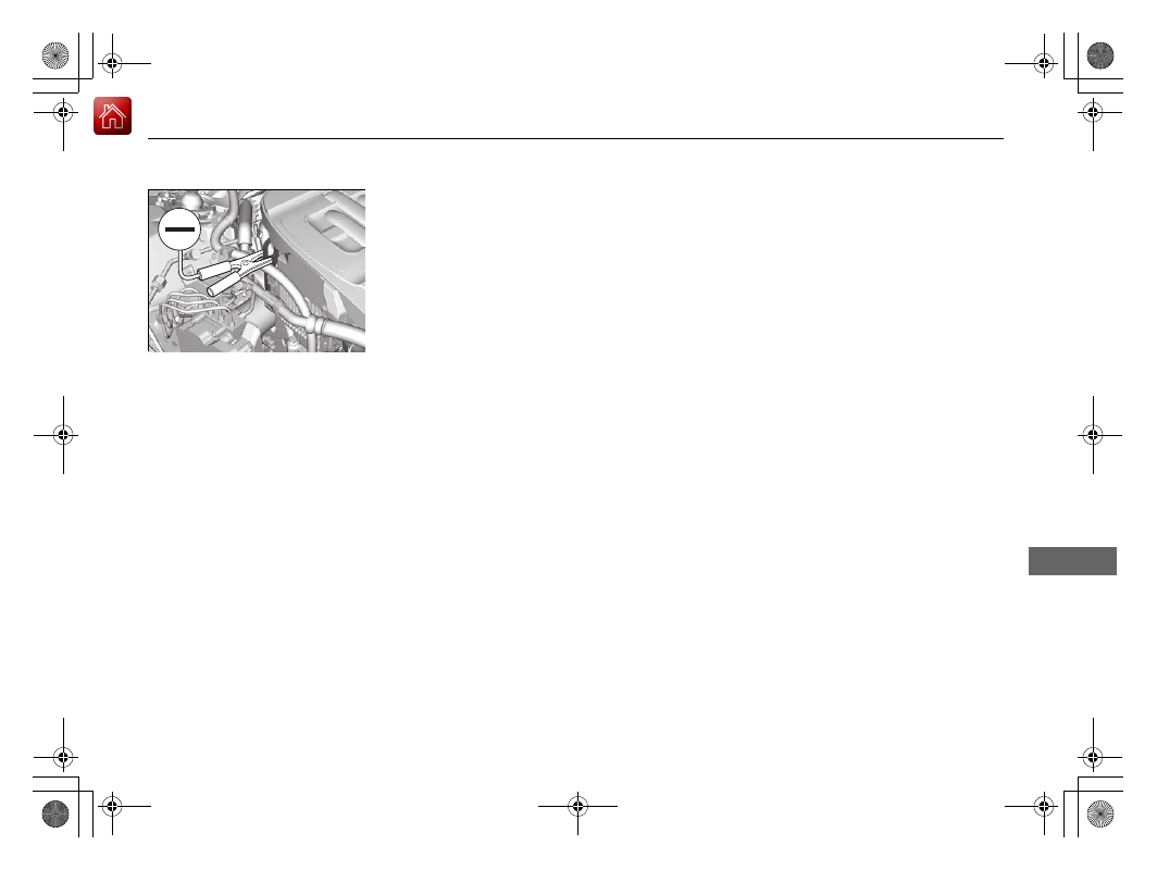
5.
Connect the other end of the second
jumper cable to the engine hanger as
shown. Do not connect this jumper cable to
any other part.
6.
If your vehicle is connected to another
vehicle, start the assisting vehicle’s engine
and increase its rpm slightly.
7.
Attempt to start your vehicle’s engine. If it
turns over slowly, check that the jumper
cables have good metal-to-metal contact.
-------------------------------------------------------------------------------------------------------------------------------------------------------------
564
uu
Jump Starting
u
Han
d
lin
g the U
n
expected
Once your vehicle’s engine has started, remove the jumper cables in the following
order.
1.
Disconnect the jumper cable from your vehicle’s ground.
2.
Disconnect the other end of the jumper cable from the booster battery
-
terminal.
3.
Disconnect the jumper cable from your vehicle’s 12-volt battery
+
terminal.
4.
Disconnect the other end of the jumper cable from the booster battery
+
terminal.
Have your vehicle inspected by a nearby service station or a dealer.
■
What to Do After the Engine Starts
-------------------------------------------------------------------------------------------------------------------------------------------------------------
565
Continued
Han
d
lin
g the U
n
expected
Overheating
How to Handle Overheating
Overheating symptoms are as follows:
•
The high temperature indicator comes on or the engine suddenly loses power.
•
Steam or spray comes out of the engine compartment.
■
First thing to do
1.
Immediately park the vehicle in a safe place.
u
Change the gear position to
(
P
and set the parking brake.
2.
Turn off all accessories and turn on the hazard warning lights.
u
No steam or spray present
: Keep the power system on and open the hood.
u
Steam or spray is present
: Turn off the power system and wait until it
subsides. Then open the hood.
1
NOTICE
Continuing to drive with the high temperature
indicator on may damage the engine.
3
WARNING
Steam and spray from an overheated
engine can seriously scald you.
Do not open the hood if steam is coming
out.
-------------------------------------------------------------------------------------------------------------------------------------------------------------
uu
Overheating
u
How to Handle Overheating
566
Han
d
lin
g the U
n
expected
■
Next thing to do
1.
Check that the cooling fan is operating and
turn the power system off once the high
temperature indicator goes off.
u
If the cooling fan is not operating,
immediately turn the power system off.
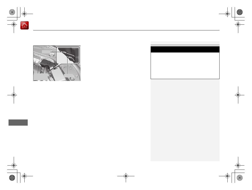
2.
Once the engine has cooled down, inspect
the coolant level and check the cooling
system components for leaks.
u
If the coolant level in the reserve tank is
low, add coolant until it reaches the
MAX
mark.
u
If there is no coolant in the reserve tank,
check that the radiator is cool. Cover the
radiator cap with a heavy cloth and open
the cap. If necessary, add coolant up to
the base of the filler neck, and put the
cap back on.
2
■
Last thing to do
Once the engine has cooled sufficiently, turn the power system on and check the
high temperature indicator. If the high temperature indicator is off, resume driving.
If it stays on, contact a dealer for repairs.
1
If the coolant is leaking, contact a dealer for repairs.
Use water as an emergency/temporary measure only.
Have a dealer flush the system with proper antifreeze
as soon as possible.
3
WARNING
Removing the radiator cap while the
engine is hot can cause the coolant to spray
out, seriously scalding you.
Always let the engine and radiator cool
down before removing the radiator cap.
Reserve
Tank
MAX
MIN
-------------------------------------------------------------------------------------------------------------------------------------------------------------
567
Han
d
lin
g the U
n
expected
Indicator, Coming On/Blinking
If the Low Oil Pressure Indicator Comes On
■
Reasons for the indicator to come on
Comes on when the engine oil pressure is low.
■
What to do as soon as the indicator comes on
1.
Immediately park the vehicle on level ground in a safe place.
2.
If necessary, turn the hazard warning lights on.
■
What to do after parking the vehicle
1.
Turn the power system off and let it sit for about three minutes.
2.
Open the hood and check the oil level.
2
3.
Turn the power system on and check the low oil pressure indicator.
u
The indicator goes off: Start driving again.
u
The indicator does not go off within 10 seconds: Turn the power
system off and contact a dealer for repairs immediately.
If the 12-Volt Battery Charging System Indicator
Comes On
■
Reasons for the indicator to come on
Comes on when the 12-volt battery is not being charged.
■
What to do when the indicator comes on
Turn off the climate control system, rear defogger, and other electrical
systems, and immediately contact a dealer for repairs.
1
If the Low Oil Pressure Indicator Comes On
NOTICE
Running the engine with low oil pressure can cause
serious mechanical damage almost immediately.
1
If the 12-Volt Battery Charging System Indicator Comes On
If you need to stop temporarily, do not turn off the
power system. Restarting the power system may
rapidly discharge the battery.
-------------------------------------------------------------------------------------------------------------------------------------------------------------
568
uu
Indicator, Coming On/Blinking
u
If the Malfunction Indicator Lamp Comes On or Blinks
Han
d
lin
g the U
n
expected
If the Malfunction Indicator Lamp Comes On or
Blinks
■
Reasons for the indicator lamp to come on or blink
•
Comes on when there is a problem with the engine emissions control
system.
•
Blinks when engine misfiring is detected.
■
What to do when the indicator lamp comes on
Avoid high speeds and immediately get your vehicle inspected at a
dealer.
■
What to do when the indicator lamp blinks
Park the vehicle in a safe place with no flammable items and wait at least
10 minutes or more with the engine stopped until it cools.
If the Brake System Indicator (Red) Comes On
■
Reasons for the indicator to come on
•
The brake fluid is low.
•
There is a malfunction in the brake system.
■
What to do when the indicator comes on while driving
Depress the brake pedal lightly to check pedal pressure.
•
If normal, check the brake fluid level the next time you stop.
•
If abnormal, take immediate action. If necessary, downshift the
transmission to slow the vehicle using regenerative braking.
1
If the Malfunction Indicator Lamp Comes On or Blinks
NOTICE
If you drive with the malfunction indicator lamp on,
the emissions control system and the engine could be
damaged.
If the malfunction indicator lamp blinks again when
restarting the engine, drive to the nearest dealer at
31 mph (50 km/h) or less. Have your vehicle
inspected.
1
If the Brake System Indicator (Red) Comes On
Have your vehicle repaired immediately.
It is dangerous to drive with low brake fluid. If there
is no resistance from the brake pedal, stop
immediately in a safe place. If necessary, downshift
the gears.
If the brake system indicator and
ABS
indicator come
on simultaneously, the electronic brake distribution
system is not working. This can result in vehicle
instability under sudden braking.
Have your vehicle inspected by a dealer immediately.
If both red and amber brake system indicators come
on, stop the vehicle in a safe place and have it
inspected by a dealer immediately.
U.S.
Canada
-------------------------------------------------------------------------------------------------------------------------------------------------------------
569
uu
Indicator, Coming On/Blinking
u
If the Electric Power Steering (EPS) System Indicator Comes On
Han
d
lin
g the U
n
expected
If the Electric Power Steering (EPS) System Indicator
Comes On
■
Reasons for the indicator to come on
•
Comes on when there is a problem with the EPS system.
•
If you depress the accelerator pedal repeatedly to increase the engine
speed while the engine is idling, the indicator comes on, and
sometimes the steering wheel becomes harder to operate.
■
What to do when the indicator comes on
Stop the vehicle in a safe place and turn on the power system again.
If the indicator comes on and stays on, immediately have your vehicle
inspected by a dealer.
If the Electric Parking Brake System Indicator Comes
On
■
Reasons for the indicator to come on
Comes on when there is a problem with the electric parking brake
system.
■
What to do when the indicator comes on
Avoid using the parking brake and immediately get your vehicle
inspected at a dealer.
■
What to do when the electric parking brake indicator comes on
or blinks at the same time.
•
Release the parking brake. If you cannot release it, immediately stop
the vehicle in a safe place and call a dealer.
•
If only the electric parking brake indicator goes off, immediately get
your vehicle inspected at a dealer.
•
If the electric parking brake indicator remains on or blinks even after
releasing the parking brake, immediately stop the vehicle in a safe
place and call a dealer.
-------------------------------------------------------------------------------------------------------------------------------------------------------------
570
uu
Indicator, Coming On/Blinking
u
If the Low Tire Pressure/TPMS Indicator Comes On or Blinks
Han
d
lin
g the U
n
expected
If the Low Tire Pressure/TPMS Indicator Comes On or
Blinks
■
Reasons for the indicator to come on or blink
A tire pressure is significantly low. If there is a problem with the TPMS or
the compact spare tire
*
is installed, the indicator blinks for about one
minute, and then stays on.
■
What to do when the indicator comes on
Drive carefully and avoid abrupt cornering and hard braking.
Stop your vehicle in a safe place. Check the tire pressure and adjust the
pressure to the specified level. The specified tire pressure is on a label on
the driver’s side doorjamb.
■
What to do when the indicator blinks, then remains on
Have the tire inspected by a dealer as soon as possible. If the compact
spare tire
*
causes the indicator to blink, change the tire to a full-size tire.
The indicator goes off after driving for a few miles (kilometers).
1
If the Low Tire Pressure/TPMS Indicator Comes On or Blinks
NOTICE
Driving on an extremely underinflated tire can cause
it to overheat. An overheated tire can fail. Always
inflate your tires to the prescribed level.
* Not available on all models
-------------------------------------------------------------------------------------------------------------------------------------------------------------
571
uu
Indicator, Coming On/Blinking
u
If the Transmission System Indicator Blinks along with the Warning Message
Han
d
lin
g the U
n
expected
If the Transmission System Indicator Blinks along
with the Warning Message
■
Reasons for the indicator to blink
The transmission is malfunctioning.
■
What to do when the indicator blinks
•
Immediately have your vehicle inspected by a dealer.
•
Change the gear position to
(
N
after you turn the power system on.
u
Check if the
(
N
position in the instrument panel and the indicator
on the
(
N
button light/blink.
u
The power system cannot be turned on unless the parking brake is
set.
2
P. 378
1
If the Transmission System Indicator Blinks along with the
Warning Message
You may not be able to turn on the power system.
Make sure to set the parking brake when parking
your vehicle.
Call a professional towing service if you need to tow
your vehicle.
2
-------------------------------------------------------------------------------------------------------------------------------------------------------------
572
Han
d
lin
g the U
n
expected
Fuses
Fuse Locations
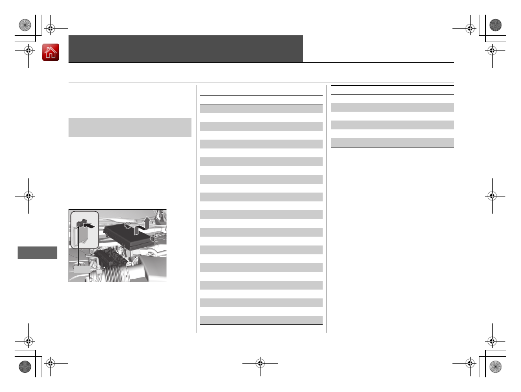
If any electrical devices are not working, set
the power mode to VEHICLE OFF and check
to see if any applicable fuse is blown.
There are four fuse boxes in the engine
compartment.
Fuse locations are shown on the fuse box
cover. Locate the fuse in question by the
fuse number and box cover number.
Located near the brake fluid reserve tank.
Push the tabs to open the box.
■
Engine Compartment Fuse
Box
Tab
■
Circuit protected and fuse rating
Circuit Protected
Amps
1
IG1A ACG FR
15 A
2
IG1A MISS SOL1
10 A
3
−
−
4
−
−
5
SMART
7.5 A
6
IG1B ECU FR
7.5 A
7
IG1B OP FR
7.5 A
8
IGP2
15 A
9
DBW
15 A
10
IGP
15 A
11
IG Coil
15 A
12
ACM
20 A
13
Headlight Washer
*
(30 A)
14
Interior Lights
10 A
15
Back Up Radio
10 A
16
Back Up
10 A
17
AFP
10 A
18
Front Washer
15 A
19
Stop
7.5 A
20 Right Headlight High Beam
10 A
21
Trunk
10 A
22
Small
15 A
23
Front Fog Lights
*
(7.5 A)
24
Left Headlight High Beam
10 A
25
IMA Motor
15 A
26 Right Headlight Low Beam
15 A
27
Left Headlight Low Beam
15 A
28
IGP2 Sub
7.5 A
29
Power Rear Sunshade
*
(20 A)
30
Heated Windshield
20 A
31
Wiper
30 A
Circuit Protected
Amps
* Not available on all models
-------------------------------------------------------------------------------------------------------------------------------------------------------------
573
uu
Fuses
u
Fuse Locations
Continued
Han
d
lin
g the U
n
expected
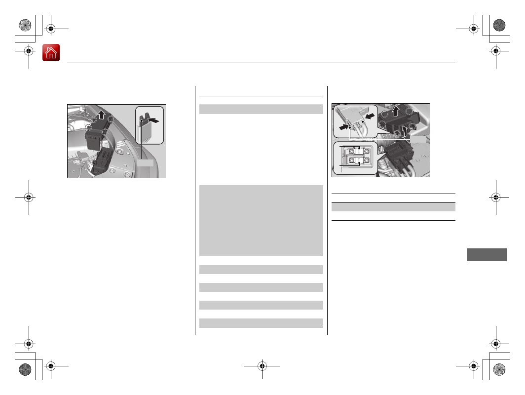
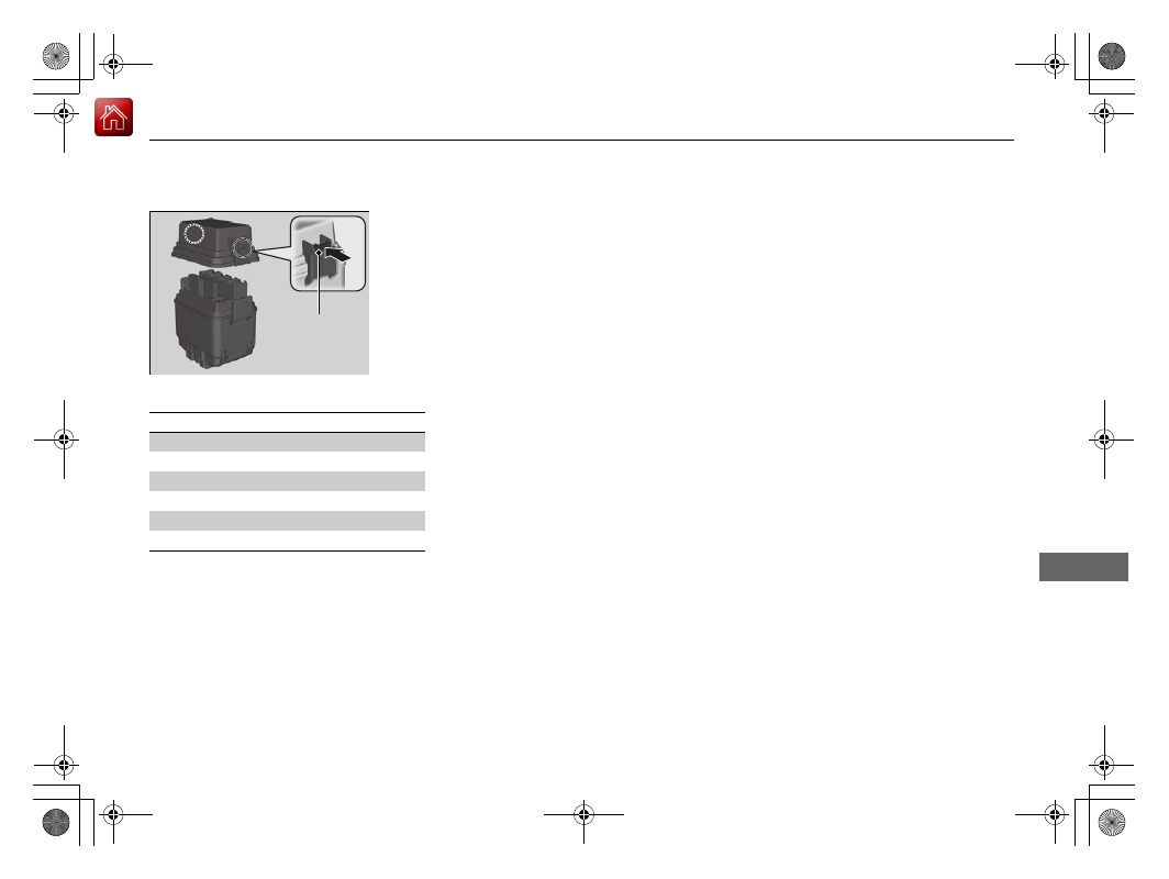
Located near the 12-volt battery. Push the
tabs to open the box.
Tab
■
Circuit protected and fuse rating
Circuit Protected
Amps
1
Main Fuse
200 A
2
−
(40 A)
Rear Defroster
40 A
DR F/B Main 1
60 A
AS F/B Main 1
60 A
R/B Main 3
50 A
AS F/B Main 2
60 A
ABS/VSA RLY
30 A
Heater Motor
40 A
3
R/B Main 1
60 A
ESB
40 A
IG Main
60 A
DR F/B Main 2
60 A
SBW
60 A
R/B Main 2
60 A
Horn & Hazard
20 A
ABS/VSA Motor
40 A
4
EOP
30 A
5
Left Electric Parking Brake
30 A
6
Right Electric Parking Brake
30 A
7
Injector
20 A
8
Hazard
15 A
9
IGA 2
7.5 A
10
−
−
11
Horn
10 A
Located near the
+
terminal on the 12-volt
battery. Push the tabs to open the box.
■
Circuit protected and fuse rating
1
2
Tab
Circuit Protected
Amps
1
Radiator Fan
50 A
2
EPS
80 A
-------------------------------------------------------------------------------------------------------------------------------------------------------------
574
uu
Fuses
u
Fuse Locations
Han
d
lin
g the U
n
expected
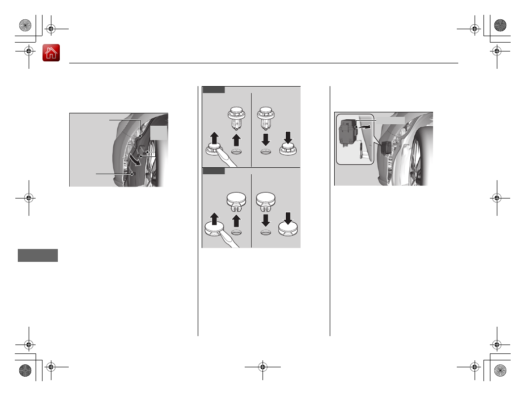
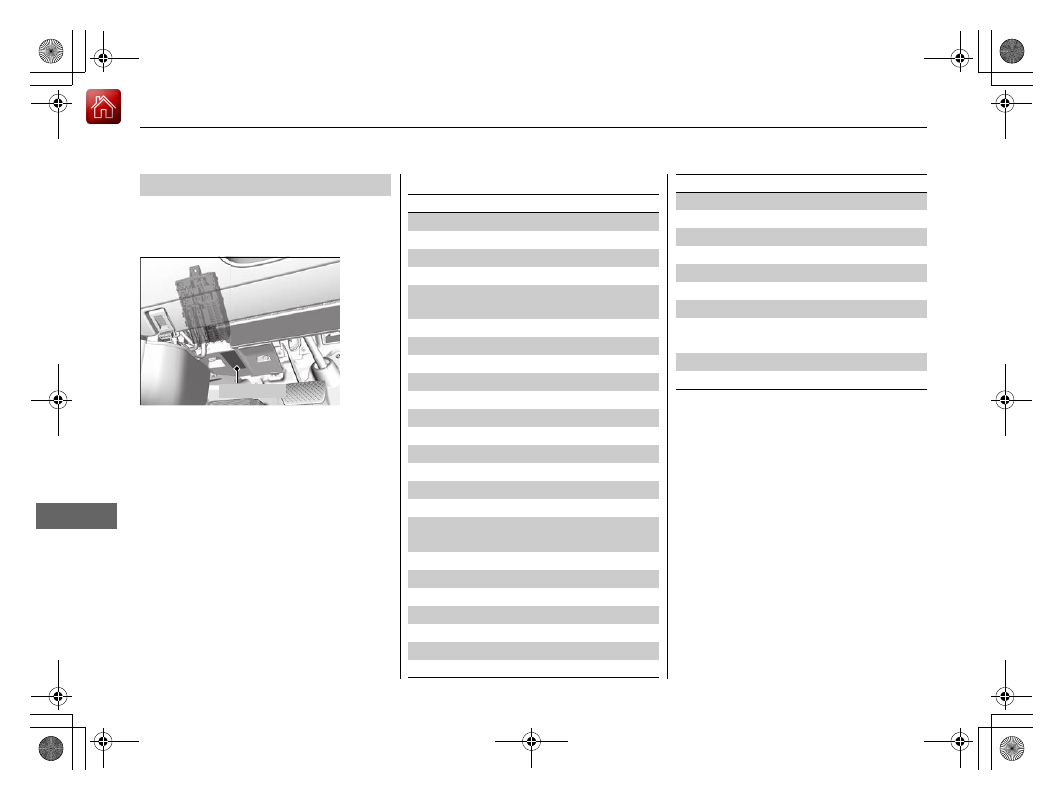
Located inside the left side of the front
bumper. Use the following procedure to
reach the box.
1.
Turn the steering wheel all the way to the
right.
2.
Remove the holding clips (A) and (B) by
inserting a flat-tip screwdriver and lifting
the center pins up.
u
Make sure to reinstall the clips after
inspecting the fuses.
u
To reinstall the clips, insert them with
the center pins raised, and push until
they are flat.
Inner Fender
Clip (A)
Clips
(B)
Clip (A)
Clip (B)
<Removing>
<Installing>
<Removing>
<Installing>
3.
Pull the inner fender back.
4.
Pull the lock tab to the direction shown in
the image and pull out the fuse box.
Lock Tab
-------------------------------------------------------------------------------------------------------------------------------------------------------------
575
uu
Fuses
u
Fuse Locations
Continued
Han
d
lin
g the U
n
expected
Push the tabs to remove the cover.
■
Circuit protected and fuse rating
Tab
Circuit Protected
Amps
1
HCA 1
20 A
2
TCU
30 A
3
HCA 2
20 A
4
STRG MOVE 1
20 A
5
−
−
6
−
−
-------------------------------------------------------------------------------------------------------------------------------------------------------------
576
uu
Fuses
u
Fuse Locations
Han
d
lin
g the U
n
expected
There are two fuse boxes in the driver’s side.
Located under the dashboard.
Fuse locations are shown on the label on
the under panel.
Locate the fuse in question by the fuse
number and label number.
■
Driver’s Side Interior Fuse Box
Fuse Label
■
Circuit protected and fuse rating
Circuit Protected
Amps
1
Driver’s Side Door Lock
10 A
2
Passenger’s Side Door Lock
10 A
3
Driver’s Door Lock
10 A
4
Driver’s Side Door Unlock
10 A
5
Passenger’s Side Door
Unlock
10 A
6
Driver’s Door Unlock
10 A
7
Door Lock
20 A
8
−
−
9
Power System 1
10 A
10
IG1 DR1
7.5 A
11
Meter
10 A
12
Passenger’s Side Fuse Box
20 A
13
ACCESSORY
7.5 A
14
−
−
15 Driver’s Power Seat Sliding
20 A
16
Moonroof
20 A
17
Rear Driver’s Side Power
Window
20 A
18
STRG MOVE 2
20 A
19
Driver’s Power Window
20 A
20
Power System 2
15 A
21
Fuel Pump
20 A
22
Power System 2
7.5 A
23
Starter Cut
7.5 A
24
IG1 DR2
7.5 A
25
Start DIAG
7.5 A
26
Air Conditioning
7.5 A
27
Daytime Running Lights
7.5 A
28
ACC Key Lock
7.5 A
29
Driver’s Lumbar Support
7.5 A
30
SMART
10 A
31
−
−
32
Driver’s Power Seat
Reclining
20 A
33
Left e-pretensioner
(20 A)
34
IG1 Box
30 A
Circuit Protected
Amps
-------------------------------------------------------------------------------------------------------------------------------------------------------------
577
uu
Fuses
u
Fuse Locations
Continued
Han
d
lin
g the U
n
expected
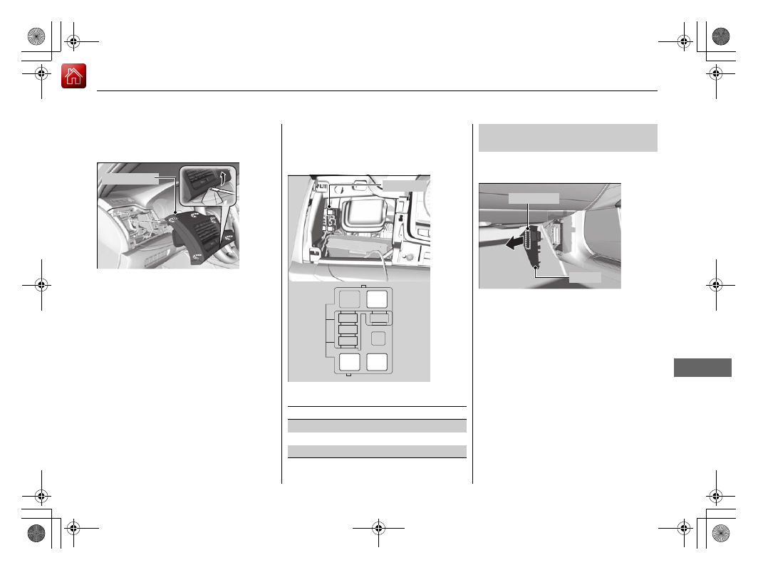
Located inside the driver’s side outer panel.
When you remove the outer panel, use the
following procedure.
1.
Pry on the lower edge of the panel using
a flat-tip screwdriver.
u
Wrap the flat-tip screwdriver with a
cloth to prevent scratches.
2.
Pull the outer panel towards you, then
remove it.
Outer Panel
Fuse locations are shown on the image
below.
Locate the fuse in question by the fuse
number in the image and chart.
■
Circuit protected and fuse rating
3
1
2
Fuse Box
Circuit Protected
Amps
1
IG Main 2
30 A
2
ST MG
30 A
3
IG Main 1
30 A
Located on the lower side panel. Take off
the cover to open.
Fuse locations are shown on the cover.
■
Passenger’s Side Interior Fuse
Box
Fuse Label
Cover
-------------------------------------------------------------------------------------------------------------------------------------------------------------
Нет комментариевНе стесняйтесь поделиться с нами вашим ценным мнением.
Текст