Acura RL (1996-2004 year). Manual — part 614
*: You can also test the switch by using the self-diagnosis function (mode 2). (See page
.)
Gauge Assembly
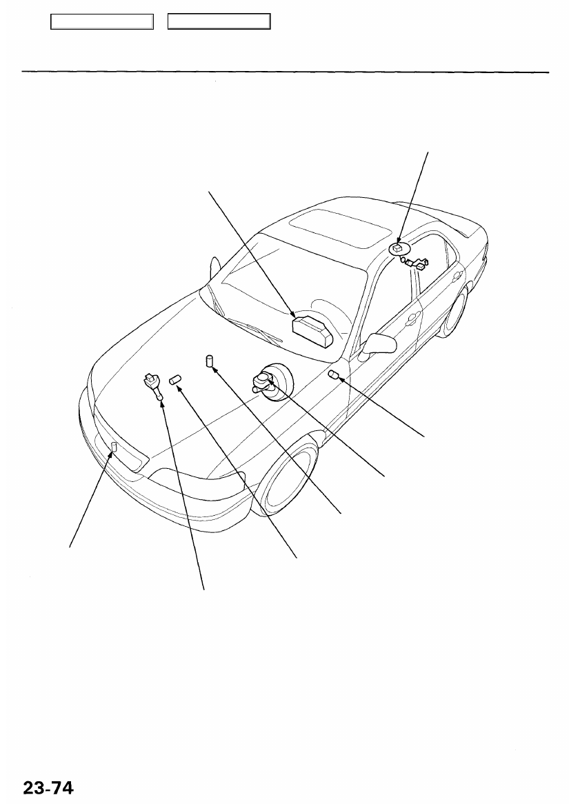
Component Location Index
GAUGE ASSEMBLY
Gauge/Terminal Locations Index, page
Select/Reset Switch Test, page
ENGINE COOLANT TEMPERATURE (ECT)
GAUGE SENDING UNIT
See
ENGINE OIL PRESSURE SWITCH*
See
VEHICLE SPEED SENSOR (VSS)*
Troubleshooting, page
OUTSIDE AIR TEMPERATURE
SENSOR
See
Main Menu
Table of Contents
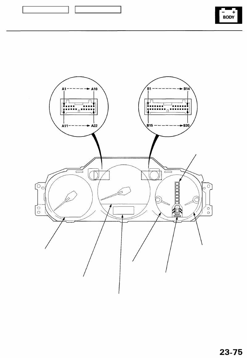
Gauge/Terminal Location Index
CONNECTOR "A" (C508)
CONNECTOR "B" (C509)
A/T GEAR POSITION
INDICATOR
See
COOLANT TEMPERATURE GAUGE:
TRIP METER/OUTSIDE
AIR TEMPERATURE INDICATOR:
SPEEDOMETER:
Indicates 60 mph at 1,026 rpm
(60 km/h at 637 rpm) of the
vehicle speed sensor(VSS).
TACHOMETER:
Indicates 100 rpm at
300 pulses per minute
of the ignition control
module (ICM).
Main Menu
Table of Contents
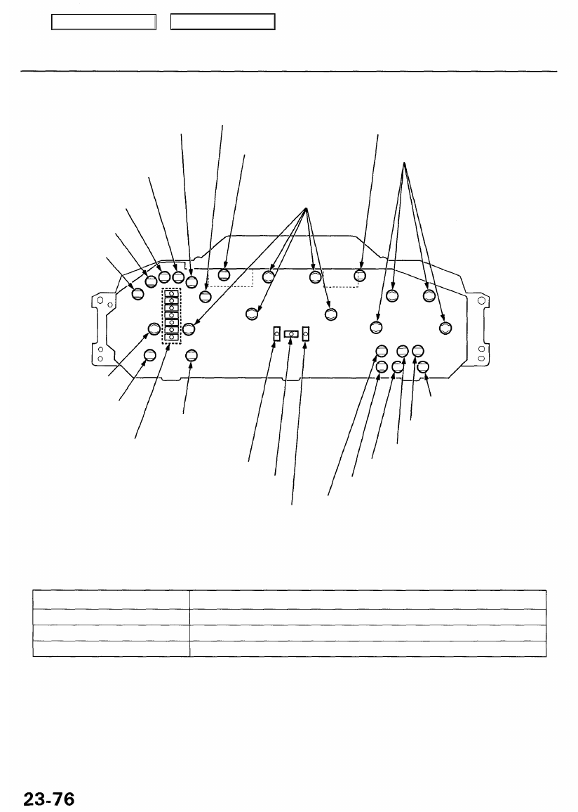
Gauge Assembly
Bulb Locations
• LIGHTS-ON INDICATOR
LIGHT (1.4 W)*
1
• SIDE AIRBAG INDICATOR
LIGHT (1.4 W)*
2
SRS INDICATOR
LIGHT (1.4 W)
RIGHT TURN SIGNAL INDICATOR
LIGHT (1.7 W)
GAUGE LIGHTS
(3.0 W x 5)
• DRL INDICATOR LIGHT
(1.4 W) (Canada)*
1
• CRUISE LIGHT(1.4 W)*
2
• IMMOBILIZER INDICATOR
LIGHT (1.4 W)*
1
• VSA SYSTEM INDICATOR
LIGHT (1.4 W)*
2
ABS INDICATOR
LIGHT (1.4 W)
SEAT BELT REMINDER
LIGHT (1.4 W)
LEFT TURN SIGNAL INDICATOR
LIGHT (1.7 W)
GAUGE LIGHTS
(3.0 W x 4)
MALFUNCTION INDICATOR LAMP
(MIL) (1.4 W)
LOW ENGINE OIL PRESSURE
INDICATOR LIGHT (1.4 W)
MAINTENANCE REMINDER LIGHT (1.4 W)
CHARGING SYSTEM LIGHT (1.4 W)
IMMOBILIZER INDICATOR LIGHT (1.4 W)*
2
• DRL INDICATOR LIGHT (1.4 W) (Canada)*
2
• LIGHTS-ON INDICATOR LIGHT (1.4 W)*
2
BRAKE SYSTEM
LIGHT (1.4 W)
A/T GEAR POSITION INDICATOR
LIGHTS (1.4 W x 7)
LOW FUEL
INDICATOR LIGHT (2 W)
TCS INDICATOR
LIGHT (1.4 W)*
1
GAUGE LIGHT
(3.0 W)
HIGH BEAM INDICATOR LIGHT (1.4 W)
• CRUISE CONTROL INDICATOR (1.4 W)*
1
• VSA ACTIVATION INDICATOR
LIGHT (1.4 W)*
2
*1: '96 - 99 models
*2:'00 - 01 models
MAINTENANCE REMINDER LIGHT
Blinking Pattern:
Miles (km)
Maintenance Reminder Light
O to about 6,000 (9,600)
Does not come on.
About 6,000 (9,600) to 7,500 (12,000)
Blinks for 10 seconds when the ignition switch is ON (II).
Comes on for 10 seconds when the ignition switch is ON (II).
After 7,500 (12,000)
If the light does not blink or does not come on, check the bulb and the speedometer operation. If the bulb and the
speedometer are OK, the gauge internal circuits must be faulty.
How to Reset:
Push the select switch and the reset switch at the same time, and hold them more than 10 seconds with the ignition switch
ON (II).
Main Menu
Table of Contents
Gauge Assembly
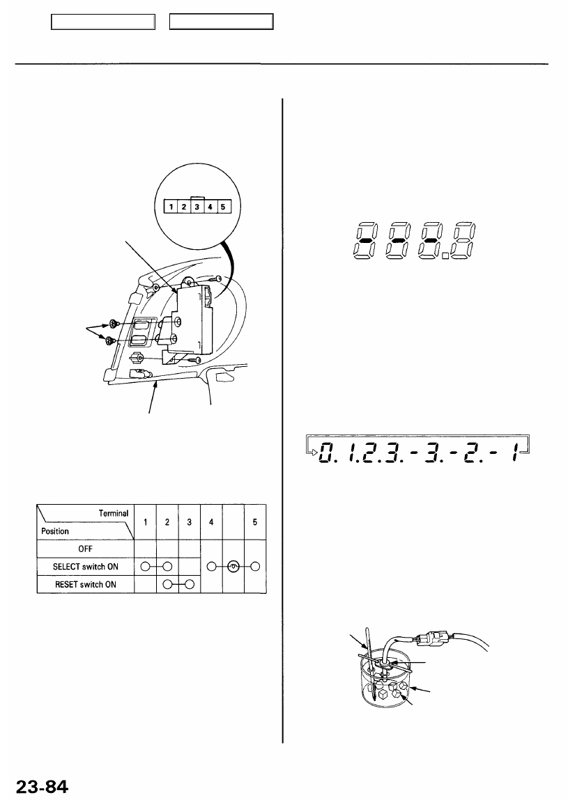
Select/Reset Switch Test
1. Remove the instrument panel (see
).
2. Disconnect the 5P connector from the switch.
SELECT/RESET
SWITCH
BULBS
(0.84 W x 2 )
INSTRUMENT PANEL
3. Check for continuity between the terminals in each
switch position according to the table.
Outside Air Temperature Indicator
NOTE: To test the outside air temperature sensor, refer
Troubleshooting
If the indicator displays "888.8", as shown, for more than
2 seconds after selecting the outside air temperature
display mode, check for an open in the wire between the
gauge and the outside air temperature sensor.
Calibration
The outside air temperature indicator's displayed
temperature can be recalibrated ±3° to meet the
customer's expectations.
1. Turn the ignition switch ON (II).
2. Select the outside air temperature mode, then push
and hold the reset button for 10 seconds. While you
continue to hold the reset button, the display will
scroll through temperature settings from +3° to -3°
as shown.
3. When the desired correction value appears on the
display, release the reset button, and the recalibrated
outside air temperature will be displayed.
NOTE: To recalibrate the display to the true tempera-
ture, remove the outside air temperature sensor, but
leave it connected. Submerge the sensor and a
thermometer in a container of ice water. Select the
calibration mode as described above, then
recalibrate the display to the true temperature.
THERMOMETER
OUTSIDE AIR TEMPERATURE
SENSOR
BEAKER
ICE
4. If the continuity checks do not agree with the table,
remove the two screws, and replace the switch.
Main Menu
Table of Contents
Нет комментариевНе стесняйтесь поделиться с нами вашим ценным мнением.
Текст