Acura RL (1996-2004 year). Manual — part 466
Differential Assembly
Reassembly (cont'd)
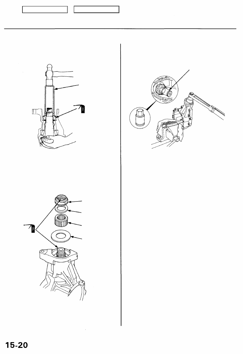
15. Apply lubricant to the tapered roller bearing, then
install it using the special tool while holding the
drive pinion as shown.
DRIVER, 40 mm I.D.
TAPERED ROLLER
BEARING
16. Install the large thrust washer, pinion hub, small
thrust washer and locknut.
NOTE: Lubricate the locknut and drive pinion threads
with gear oil.
LOCKNUT
THRUST WASHER
PINION HUB
THRUST WASHER
17. Hold the drive pinion with a 1 1/4" (32 mm) hex bit
and socket as shown.
1 1/4" (32 mm) HEX BIT
and SOCKET
(Commercially available)
18. Tighten the locknut to 216 N-m (22 kgf-m, 159 Ibf-ft),
and measure the tapered roller bearing preload
(Tp).
NOTE: Rotate the drive pinion several times to
assure proper tapered roller bearing contact.
Standard:
New Bearing: 1.82 - 2.49 N-m
(18.6 - 25.4 kgf-cm, 16.1 - 22.0 Ibf-in)
Reused Bearing: 1.42 - 1.91 N-m
(14.5 -19.5 kgf-cm, 12.6 - 16.9 Ibf-in)
• If the tapered roller bearing preload exceeds the stan-
dard, replace the pinion spacer.
• If the tapered roller bearing preload is less than the
standard, adjust by tightening the locknut a little at a
time, but keep the torque within 216 - 313 N-m (22 -
32 kgf-m, 159 - 231 Ibf-ft). If this not possible, replace
the pinion spacer.
Main Menu
Table of Contents
19. Clean the ring gear teeth, then paint them lightly and
evenly with Prussian Blue (on both sides of each
tooth).
20. Install the differential carrier into the differential
case, and reinstall the differential case cover.
21. Install the bolts and tighten in a crisscross pattern in
several steps.
Torque: 44 N-m (4.5 kgf-m, 33 Ibf-ft)
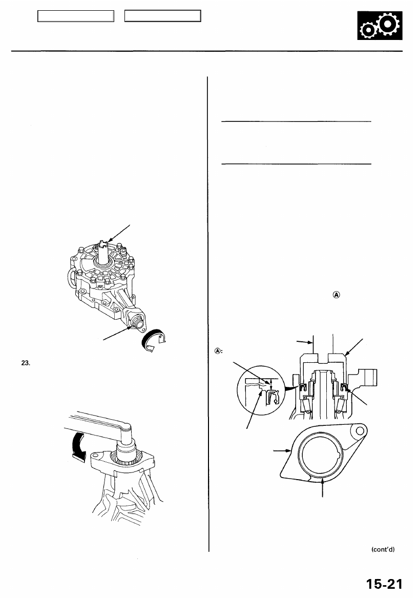
22. Install the special tool as shown. Rotate the drive
pinion in both directions so that the ring gear rotate
one full turn in both directions. During this opera-
tion resistance should be applied to the ring gear.
LOCKNUT SOCKET,
36 x 41 mm
DRIVE
PINION
Remove the special tool, and use a dial-type torque
wrench on the drive pinion to check total bearing
preload. The total bearing preload should exceed
the drive pinion bearing preload by the amount
shown in the next column.
NOTE: Rotate the drive pinion several times to
ensure proper bearing contact.
=0.94 -1.07 N-m (9.6 -10.9 kgf-cm, 8.33 - 9.46 Ibf-in)
If the total bearing preload is not within the standard,
correct it by increasing or decreasing the preload on the
carrier bearings as needed. If there is too much preload,
decrease the shim thickness equal amounts on both
sides. If there is not enough preload, increase the shim
thickness equal amounts on both sides.
NOTE: Be sure the same amount of shim thickness is
added or subtracted from both sides, so that the tooth
contact pattern and backlash are not affected.
24. Install the oil seal using the special tools as shown.
NOTE: Make sure that distance is correct.
DRIVER
PINION COVER DRIVER
ATTACHMENT
15.5-16.0 mm
(0.61 - 0.63 in)
OIL SEAL
Replace.
PROCESS SURFACE
BASE SURFACE
PROCESS SURFACE
= 1.04 -1.26 N-m (10.6 -12.8 kgf-cm, 9.2 -11.1 Ibf-in)
Reused differential carrier tapered roller bearing:
Total bearing preload (from step 23)
- Tp (from step 18)
Standard:
New differential carrier tapered roller bearing:
Total bearing preload (from step 23)
-Tp (from step 18)
Main Menu
Table of Contents
Differential Assembly
Reassembly (cont'd)
25. Hold the differential assembly using a bench vise
with soft jaws as shown.
Inspection
hole
SOFT JAWS
LOCKNUT SOCKET,
36 x 41 mm
26. Align a backlash inspection hole with the oil filler
plug hole, and install the special tools as shown.
27. Measure backlash on the differential carrier using
the special tools as shown. After measuring, remove
the dial gauge and turn the differential carrier one
full turn, then remeasure the backlash.
Standard: 0.06 - 0.14 mm (0.002 - 0.006 in)
The difference between the two measurements
taken must not exceed 0.06 mm (0.002 in).
LOCKNUT SOCKET,
36 x 41 mm
28. If the backlash is less than the standard, adjust the
).
29. Remove the differential case cover, and check the
tooth contact pattern (face and flank). If the tooth
contact is not correct, adjust ring gear contact (see
).
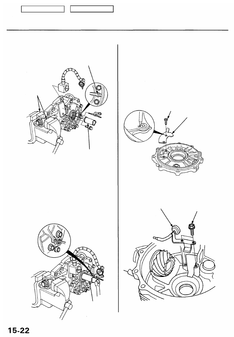
30. After all adjustments are made, install the breather
plate and stake the screw heads in the groove as
shown.
SCREW Replace.
12 N-m (1.2 kgf-m, 8.7 Ibf-ft)
BREATHER
PLATE
31. Remove the differential carrier, then install the oil
guide pipe.
6 x 1.0 mm
OIL GUIDE 12 N-m (1.2 kgf-m,
PIPE
8.7 Ibf-ft)
Main Menu
Table of Contents
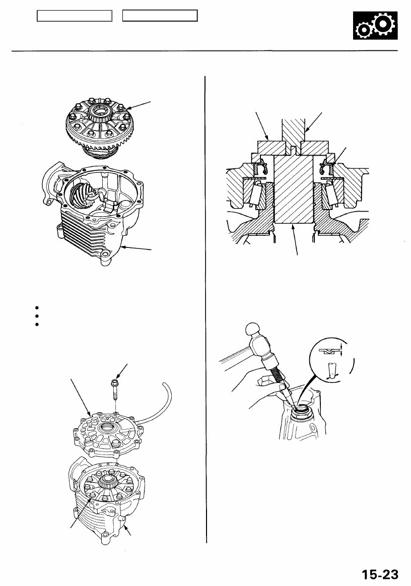
32. Install the differential carrier in the differential case.
DIFFERENTIAL
CARRIER
DIFFERENTIAL
CASE
DIFFERENTIAL
CARRIER
DIFFERENTIAL CASE
34. Install the oil seal using the special tools as shown.
DRIVER ATTACHMENT
DRIVER
OIL SEAL
Replace.
PILOT, 32 x 50 mm
35. Stake the locknut tab into the groove.
1.0 mm (0.04 in)
3.5 mm (0.14 in)
33. Install the differential case cover, and tighten the
bolts in a crisscross pattern in several steps.
NOTE:
Use liquid gasket (P/N 08718 - 0001).
Remove any dirt and oil from the sealing surface.
If 20 minutes have passed after applying liquid
gasket, reapply it, assemble the housings, and
allow it to cure at least 20 minutes after assembly
before filling differential with oil.
10 x 1.25 mm
44 N-m (4.5 kgf-m, 33 Ibf-ft)
DIFFERENTIAL
CASE COVER
Main Menu
Table of Contents
Нет комментариевНе стесняйтесь поделиться с нами вашим ценным мнением.
Текст