Acura RL (1996-2004 year). Manual — part 196
+
–
2004 American Honda Motor Co., Inc.
Connector Views
1 BLK
2 BLU
3 YEL
4 BLK/YEL
5 BLK/YEL
6 RED
7 WHT
(Front peak hold reset output)
8 BLK
1
2
4
8
6
5
3
7
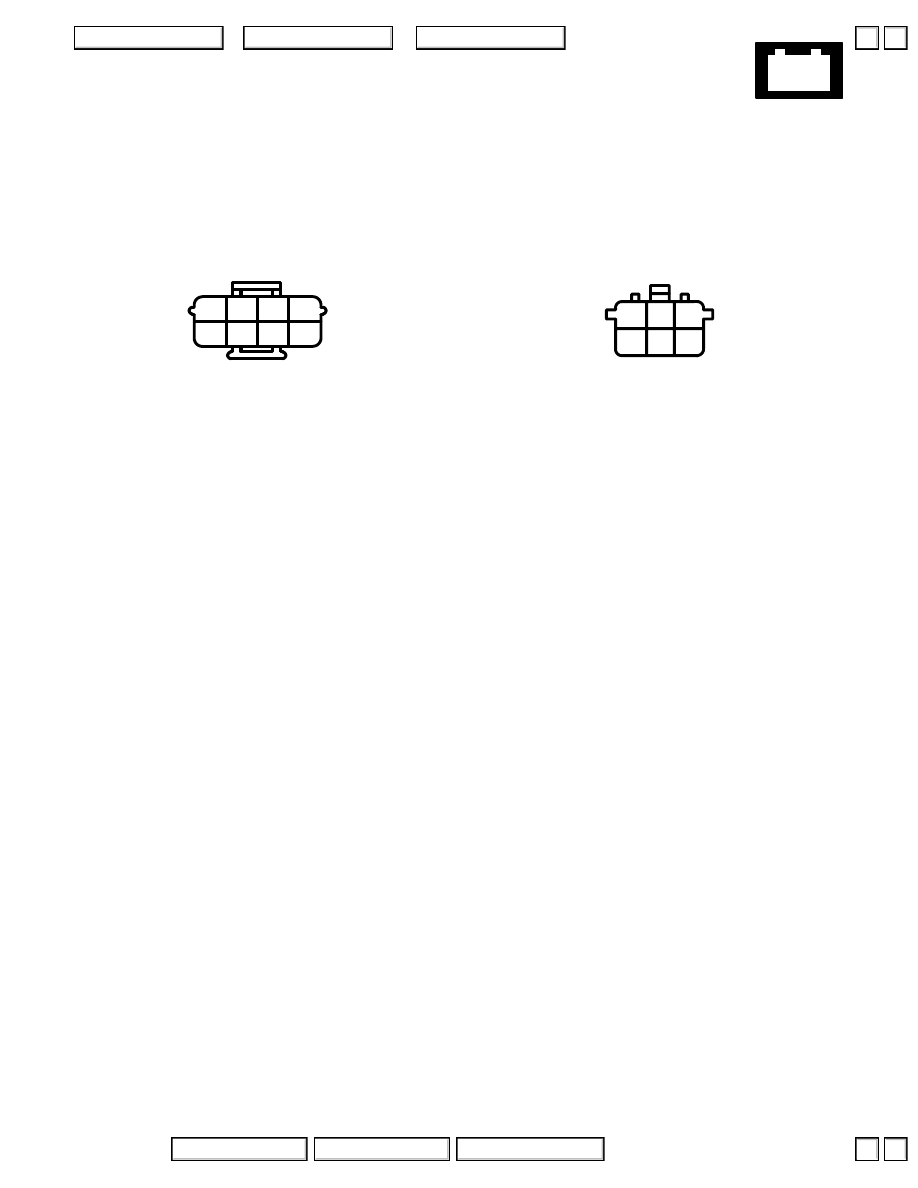
101. Spark Plug Voltage Detection Module
– Right side of engine compartment
Connector A
– Gray
– On right engine compartment wire harness
1 GRN
2 BLU
3 YEL
4 RED
5 WHT
6 BLK
2
3
6
5
1
4
Connector B
– Gray
– On engine wire harness
▲
▼
▲
▼
+
–
2004 American Honda Motor Co., Inc.
Connector Views
1
2
3
4 WHT/RED
5 YEL/RED
6 YEL
7
8 BLK
1
3
4
6
7
8
2
5
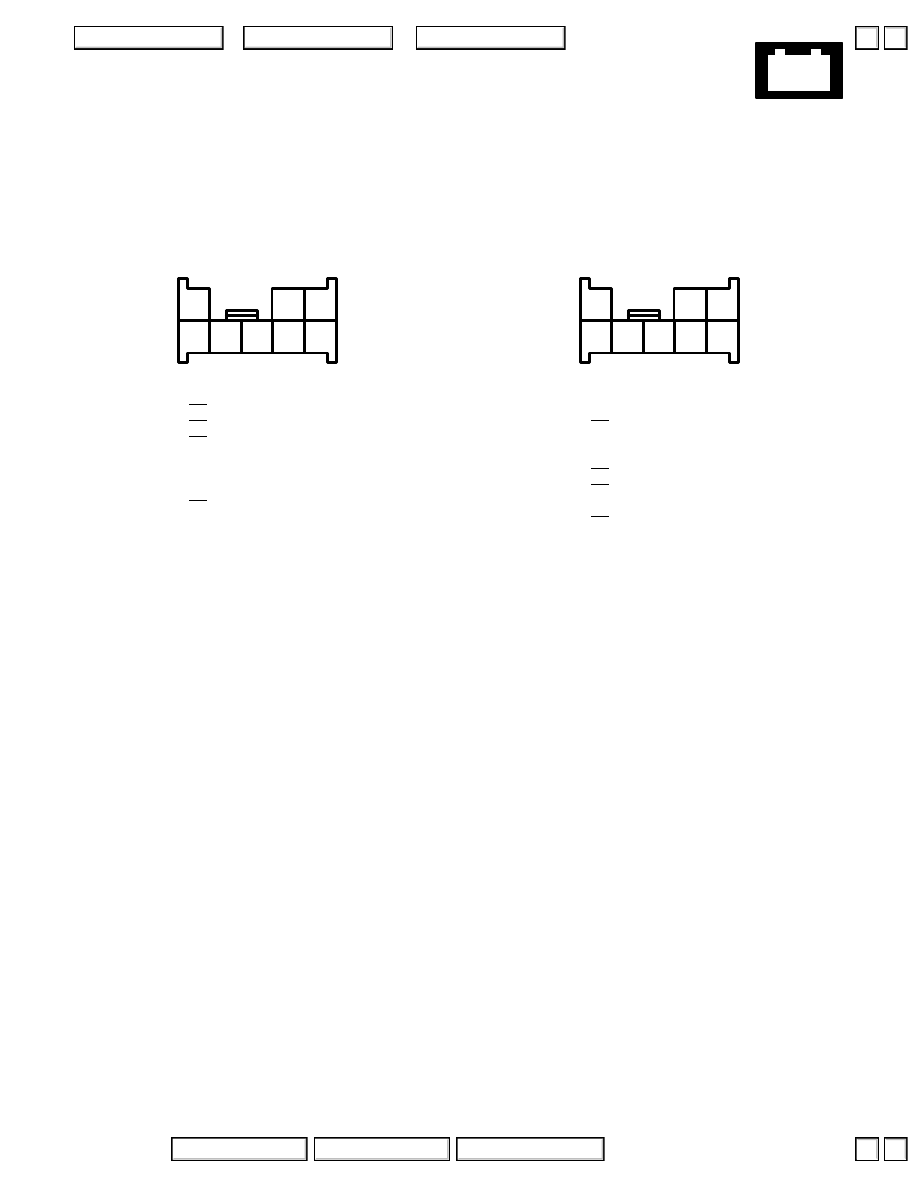
102. Front Passenger’s Power Seat Switch
– Gray
– On front passenger’s power seat wire harness
– Right side of front passenger’s seat
Connector A
2
3 RED
4 BLK
8
1
3
4
6
7
8
2
5
Connector B
▲
▼
▲
▼
+
–
2004 American Honda Motor Co., Inc.
Connector Views
2 PNK/BLU
5 RED
7 BLK
8 BLU/RED
(Blower motor control feedback)
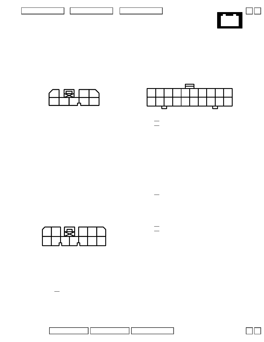
103. Climate Control Unit
– Center of dash
– On A/C wire harness
Connector A
’96-’03:
– Gray
4
5
6
7
8
1
3
2
2 RED/BLK
4 LT GRN
5 BRN/WHT
6 WHT/YEL
7 RED
8 BLU/RED
9
10 BLK
11 PNK/BLU
12 YEL
’04:
– Gray
9
8
10
7
6
12
11
1
5
2
4
3
1 ORN
2
3
4 BRN
(Evaporator temperature input)
5 BRN/WHT
(Outside air temperature input)
6 BRN/BLK
7 BLU
8 LT GRN/RED
9 RED/YEL
10 RED
11 ’99-’03 Navigation: YEL/GRN
12 YEL/BLK
13 LT GRN
(Blower motor high relay control)
14 LT GRN/BLK
15 PNK/BLK
16 WHT/RED
17 RED/WHT
18
19 GRN/RED
20 GRN/WHT
11
12
13
14
15
16
17
18
19
20
1
2
3
4
5
6
7
8
9
10
Connector B
’96-’03:
– Black
1
2
3 BRN
(Evaporator temperature input)
4 BRN/WHT
(Outside air temperature input)
5 BRN/BLK
6 YEL/BLK
7 LT GRN
(Blower motor high relay control)
8 GRN/RED
9 LT GRN/RED
10 RED
11 BLK/WHT
12 LT GRN/BLK
13 PNK/BLK
14 WHT/RED
15 RED/WHT
16 ORN
17 YEL/GRN
18 GRN/WHT
19 BLU
20 RED/YEL
’04:
– Black
▲
▼
▲
▼
+
–
2004 American Honda Motor Co., Inc.
Connector Views
11
12
13
14
15
16
17
18
19
20
1
2
3
4
5
6
7
8
9
10
1
2
3
4 BLK
5
6
7 BLU
8 WHT
9 RED
10 BRN/YEL
11
12
13 ORN
14 WHT
15
16 GRY/BLU
17 PNK
18 YEL
19 BRN
20 BLU
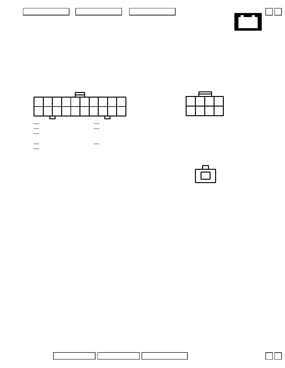
104. Navigation Unit
– Left front of trunk
’96-’99:
Connector A
– Black
– On right side wire harness
2 WHT/YEL
3 WHT/BLU
4 BLK
5 GRN/BLK
6 BLU/WHT
7 GRN/RED
8 BLU/GRN
Connector B
– Black
– On right side wire harness
Connector C
– Black
– To GPS antenna
5
6
7
8
1
2
3
4
1
2
▲
▲
Нет комментариевНе стесняйтесь поделиться с нами вашим ценным мнением.
Текст