Acura RL (1996-2004 year). Manual — part 195
+
–
2004 American Honda Motor Co., Inc.
Connector Views
8
9 10
4
5
6
7
1
2
3
20
19
29 30 31 32
34 35 36
33
37 38 39
40 41 42
12 13 14
11
16 17 18
15
22 23 24
21
26 27 28
25
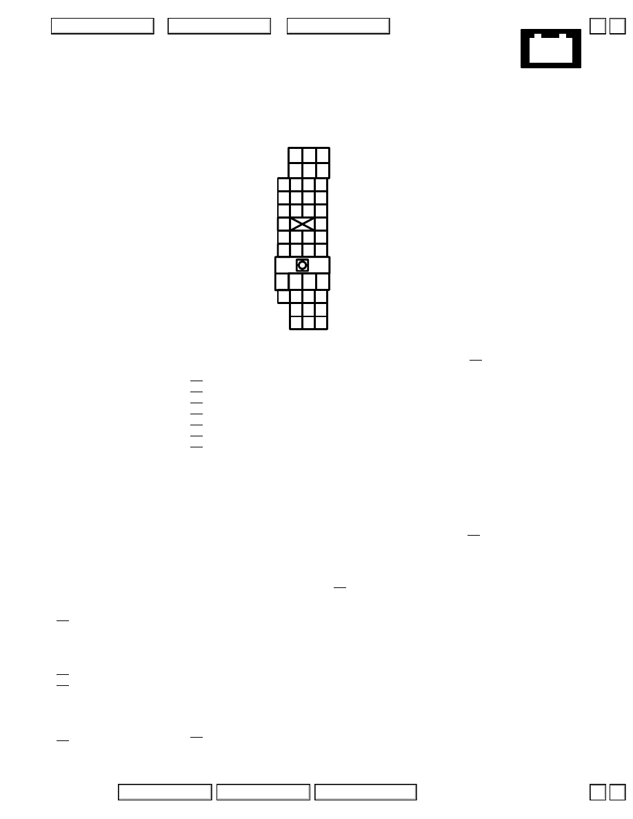
Except ’02-’03:
1 BLU/BLK
2 YEL/RED
3 WHT/BLU
4 BLK/RED
5 WHT/RED
6 WHT/YEL
7 GRN/YEL
’97-’01 Bose:
8 GRY/RED
Standard:
’97-’01 Bose:
9
10 GRN/RED
11 BLK
12 LT GRN/BLK
13
14
15 GRN/WHT
16 GRN/RED
17 GRN/RED
18 GRN/WHT
19
20 BLU/RED
21
22
23
24
25
26
27
28 ’98-’01: RED/BLK
29 RED
’97-’01 Bose:
30 BRN
’97-’01 Bose:
31 BLK
32 BLK/GRN
33 BLU/RED
34 RED/BLK
35 BRN/WHT
36 GRY
37 GRN
38 BRN
39 YEL
40 BLU
41 ’98-’01: RED
42
97.
C445
– Gray
– Above right kick panel, in access hole
– Connects main wire harness to passenger’s door wire harness
’02-’04 USA:
2 YEL/RED
3 WHT/BLU
4 BLK/RED
5 WHT/RED
6 WHT/YEL
7 GRN/YEL
8 GRY/RED
9 BLU
10 GRN/RED
11 BLK
12 LT GRN/BLK
13 GRY
14 BRN
15 GRN/WHT
16 GRN/RED
17 GRN/RED
18 GRN/WHT
19
20 BLU/RED
21
22 YEL
23 GRN/WHT
24 BLK/WHT
25 YEL
26 BLU
27 YEL/BLK
28 RED/BLK
29 RED
30 BRN
31 BLK
32 BLK/GRN
33 BLU/RED
35 BRN/WHT
36
37 LT GRN/RED
38 RED/WHT
39 BLU/GRN
40 BLU/ORN
41 RED
42 WHT/YEL
▲
▼
▲
▼
+
–
2004 American Honda Motor Co., Inc.
Connector Views
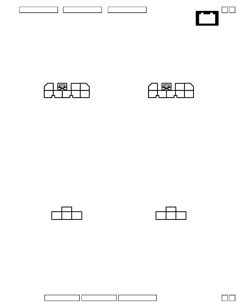
98.
Immobilizer Control Unit
– Underside of steering column
– Gray/White
– On main wire harness
’96-’98:
Connector A
3 WHT/RED
4 BLK/YEL
5 PNK
(Immobilizer indicator control)
6 WHT
7 GRN/RED
8 BLK
Connector B
– White
– On immobilizer receiver jumper
1 WHT
2 BLK
3 ORN
4
5
6
7
8
1
3
2
1
2
3
’99-’04:
Connector A
3 WHT/RED
4 YEL/BLK
5 PNK
(Immobilizer indicator control)
6 WHT
7 GRN/RED
8 BLK
Connector B
– White
– On immobilizer receiver jumper
1 WHT
2 BLK
3 ORN
4
5
6
7
8
1
3
2
1
2
3
▲
▼
▲
▼
+
–
2004 American Honda Motor Co., Inc.
Connector Views
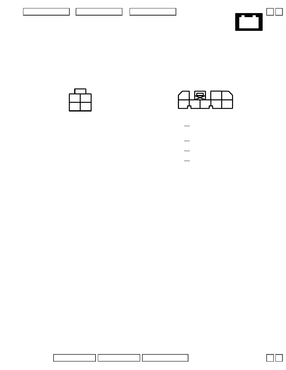
2 YEL
3 YEL/BLK
4 BLK/YEL
1
2
3
4
99.
PGM-FI Main Relay
– Right of steering column
Connector A
– Brown
– On main wire harness
1
2 YEL/GRN
3 BLU/RED
4
5 RED/WHT
6
7 BLK
8
4
5
6
7
8
1
3
2
Connector B
– Gray/White
– On main wire harness
▲
▼
▲
▼
+
–
2004 American Honda Motor Co., Inc.
Connector Views
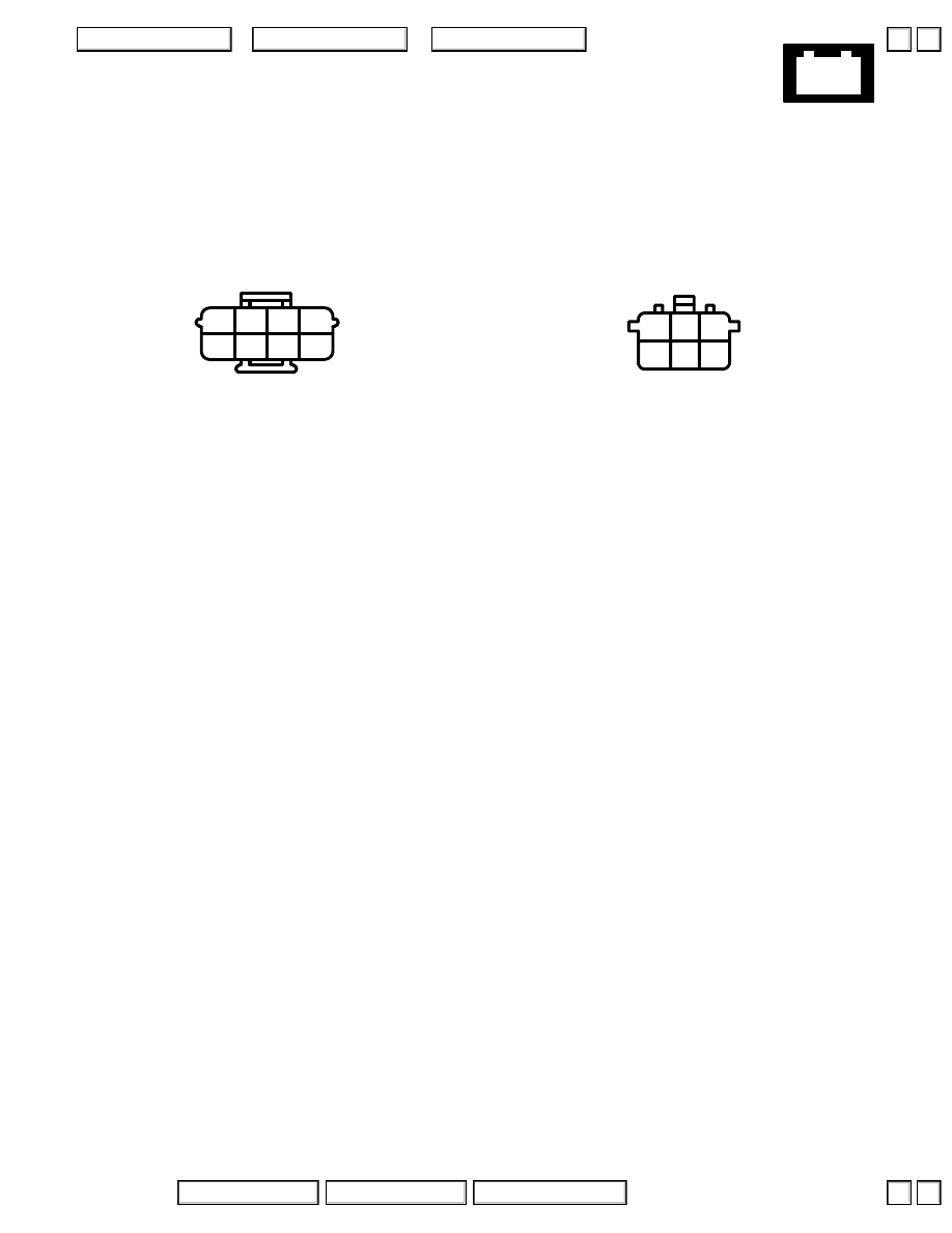
2 BLK
3 WHT/GRN
4 WHT
5 WHT/RED
6 RED/GRN
7 BLK
8 WHT/BLU
1
2
4
8
6
5
3
7
100. Ignition Control Module (ICM)
– Right front of engine
Connector A
– Gray
– On engine wire harness
1 PNK
2 BRN
3 BLU
4 GRN
6 RED
2
3
6
5
1
4
Connector B
– Gray
– On engine wire harness
▲
▼
▲
▼
Нет комментариевНе стесняйтесь поделиться с нами вашим ценным мнением.
Текст