Acura RL (1996-2004 year). Manual — part 395
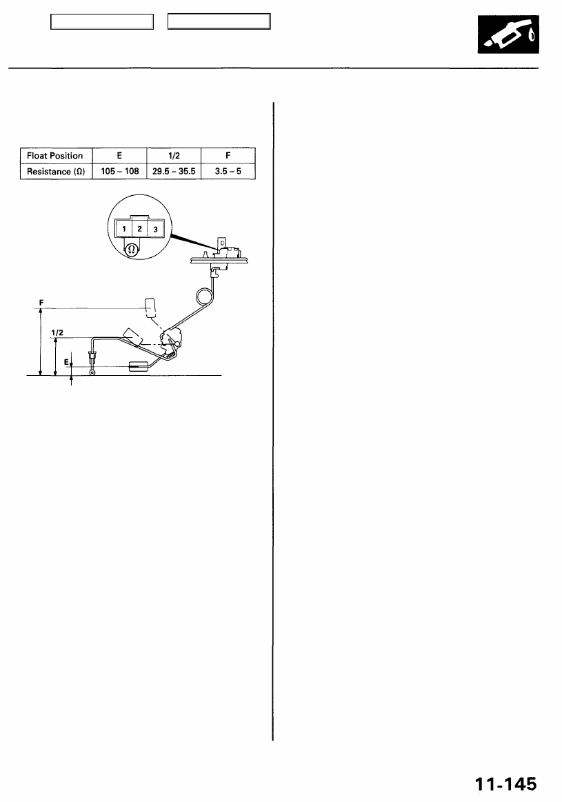
5. Measure the resistance between the No. 1 and No. 2
terminals at E (EMPTY), 1/2 (HALF FULL) and F (FULL)
by moving the float.
Terminal side of
male terminals
Top of the workbench (Bottom of the fuel tank)
If you do not get the above readings, replace the fuel
gauge sending unit.
Main Menu
Table of Contents
Low Fuel Indicator System
Indicator Light Testing
1. Check the No. 13 METER (7.5 A) fuse in the under-
fuse/relay box, METER (15 A) fuse in the under-
fuse/relay box and gauge relay before testing.
2.
the vehicle on level ground.
Do not smoke while working on the
fuel system. Keep open flame away from the work
area. Drain fuel only into an approved container.
• If the light comes on within 4 minutes, go to step
8.
• If the light does not come on within 4 minutes,
go to step 5.
5. Remove the rear seat cushion (see
).
6. Remove the fuel tank access panel from the floor,
and disconnect the 3P connector from the fuel gauge
sending unit.
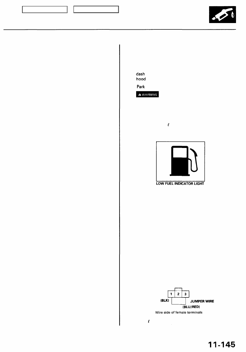
7. Connect the No. 1 and No. 3 terminals with a jumper
wire.
• if the light comes on, check the sending unit.
• If the light does not come on, check for:
— an open in the BLU/RED wire between the fuel
unit and fuel gauge assembly.
— blown bulb.
— poor ground (G652).
FUEL GAUGE SENDING UNIT CONNECTOR IC723)
should go off within four minutes.
8. Add 4
of fuel (1.1 U.S. Gal. 0.9 Imp. Gal). The light
3. Drain the fuel into an approved container. Then
install the drain bolt with a new washer.
4.
and turn the ignition switch ON (II). The low fuel indi-
cator light should come on within 4 minutes.
Add less than 8.5
(2.2 U.S. Gal. 1.8 Imp. Gal) of fuel,
Main Menu
Table of Contents
Fuel Supply System
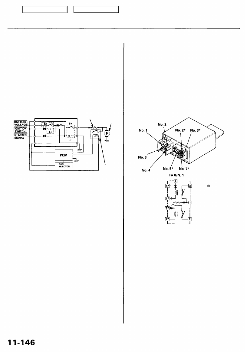
PGM-FI Main Relay
Description
This PGM-FI main relay is located behind the dashboard
lower cover. The PGM-FI main relay actually contains
two individual relays. One relay is energized whenever
the ignition is on. It supplies battery voltage to the PCM,
power to the fuel injectors, and power for the second
relay. The second relay is energized for 2 seconds when
the ignition is switched on, and when the engine is run-
ning. It supplies power to the fuel pump.
PGM-FI
MAIN RELAY
FUEL
PUMP
RELAY
Relay Testing
NOTE: If the engine starts and continues to run, the PGM-
FI main relay is OK.
1. Remove the PGM-FI main relay.
2. Attach the battery positive terminal to the No. 3*
terminal and the battery negative terminal to the
No. 2* terminal of the PGM-FI main relay. Then
check for continuity between the No. 5* terminal and
No. 2 terminal of the PGM-FI main relay.
• If there is continuity, go on to step 3.
• If there is no continuity, replace the relay and
retest.
*: 8P CONNECTOR
To FUEL PUMP
3. Attach the battery positive terminal to the No. 4 ter-
minal and the battery negative terminal to the No.
7* terminal of the PGM-FI main relay. Then check
that there is continuity between the No. 3 terminal
and No. 1 terminal of the PGM-FI main relay.
• If there is continuity, go on to step 4.
• If there is no continuity, replace the relay and
retest.
4. Attach the battery positive terminal to the No. 1 ter-
minal and battery negative terminal to the No. 2*
terminal of the PGM-FI main relay. Then check that
there is continuity between the No. 5* terminal and
No. 2 terminal of the PGM-FI main relay.
• If there is continuity, the relay is OK;
If the fuel pump still does not work, go to Harness
Testing on the next page.
• If there is no continuity, replace the relay and
retest.
To PCM CONNECTOR
TERMINAL A4
To ST. SWITCH
To GROUND
To IGN. 1
To BAT
To PCM
CONNECTOR TERMINALS
A13 and B1
FUEL PUMP
RESISTOR
FUEL PUMP
Main Menu
Table of Contents
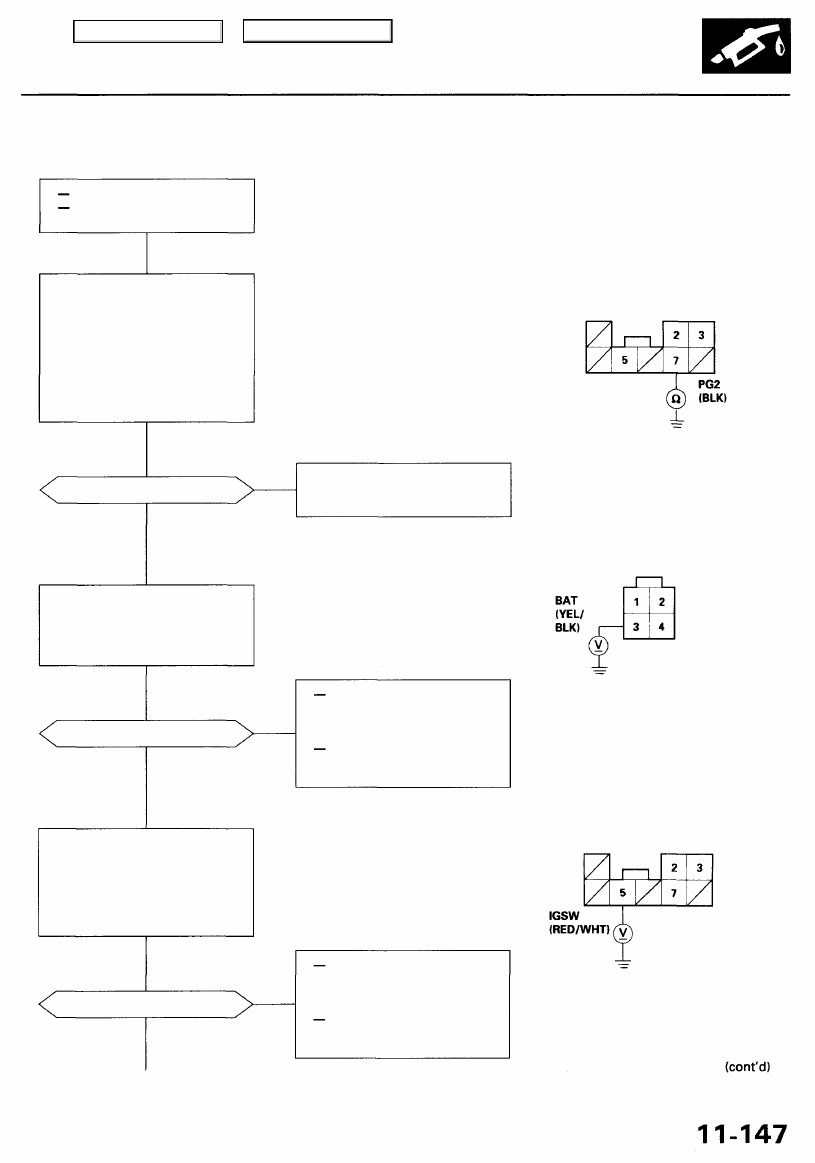
Troubleshooting Flowchart
Check for an open or short in the
wire (BAT line):
Measure voltage between the
PGM-FI main relay 4P connector
terminal No. 3 and body ground.
Is there battery voltage?
YES
Check for an open or short in the
wire (IGSW line):
1. Turn the ignition switch ON (II).
2. Measure voltage between the
PGM-FI main relay 8P connec-
tor terminal No. 5 and body
ground.
Is there battery voltage?
YES
PGM-FI MAIN RELAY 8P CONNECTOR (C433)
Wire side of female terminals
NO
Repair open in the wire between
the PGM-FI main relay and G101
(located at middle of engine).
NO
Repair open or short in the
wire between the PGM-FI
main relay and the No. 6 ECU
(PCM) (20 A) fuse.
Replace the No. 6 ECU (PCM)
(20 A) fuse in the under-dash
fuse/relay box.
PGM-FI MAIN RELAY 4P CONNECTOR (C432)
Wire side of female terminals
NO
Repair open or short in the
wire between the PGM-FI
main relay and the No. 22
FUEL PUMP (20 A) fuse.
Replace the No. 22 FUEL PUMP
(20 A) fuse in the under-dash
fuse box.
YES
Is there continuity?
Engine will not start.
Inspection of PGM-FI main
relay and relay harness.
Check for an open in the wire (PG1
line):
1. Turn the ignition switch OFF.
2. Disconnect the PGM-FI main
relay 4P connector and 8P
connector.
3. Check for continuity between
the PGM-FI main relay 8P
connector terminal No. 7 and
body ground.
Main Menu
Table of Contents
Нет комментариевНе стесняйтесь поделиться с нами вашим ценным мнением.
Текст