Acura RL (1996-2004 year). Manual — part 396

Fuel Supply System
PGM-FI Main Relay (cont'd)
Check for an open in the wire
(IGSW line):
Measure voltage between the
PGM-FI main relay 4P connector
terminal No. 4 and body ground.
Is there battery voltage?
YES
Check for an open or short in the
wire (STS line):
1. Turn the ignition switch to the
START (III) position (trans-
mission in or position).
2. Measure the voltage between
the PGM-FI main relay 8P con-
nector terminal No. 3 and
body ground.
Is there battery voltage?
YES
Check for an open in the wire
(FLR1 line):
1. Turn the ignition switch OFF.
2. Disconnect the PCM connec-
tor A (26 P) from the PCM.
3. Check for continuity between
the PGM-FI main relay 8P
connector terminal No. 2 and
PCM connector terminal A4.
PGM-FI MAIN RELAY 4P CONNECTOR (C432)
IGSW
(BLK/YEL)
NO
Repair open or short in the
wire between the PGM-FI
main relay and the No. 25 IG
COIL (30 A) fuse.
Replace the No. 25 IG COIL
(30 A) fuse in the under-dash
fuse/relay box.
Wire side of female terminals
PGM-FI MAIN RELAY 8P CONNECTOR (C433)
NO
Repair open or short in the
wire between the PGM-FI
main relay and the No. 14
STARTER SIGNAL (7.5 A) fuse.
Replace the No. 14 STARTER
SIGNAL (7.5 A) fuse in the
under-dash fuse box.
Wire side of female terminals
Is there continuity?
Repair open in the wire between
the PCM (A4) and the PGM-FI
main relay.
PCM CONNECTOR A (26P)
Wire side of female terminals
YES
NO
Main Menu
Table of Contents
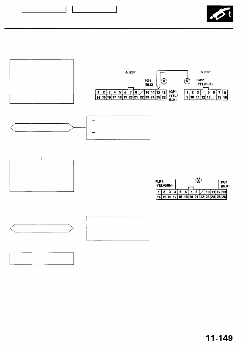
Check for an open in the wires
(IGP1, IGP2 lines):
1. Reconnect the PCM connector
A (26P).
2. Reconnect the PGM-FI main
relay 4P and 8P connectors.
3. Turn the ignition switch ON (II).
4. Measure voltage between
PCM connector terminals
A13, B1, and A12.
PCM CONNECTORS
Wire side of female terminals
Is there battery voltage?
YES
Repair open in the wire
between the PCM (A13, B1)
and the PGM-FI main relay.
Replace the PGM-FI main
relay.
Check for an open in the PCM:
1. Turn the ignition switch OFF.
2. Measure voltage between
PCM connector terminals A4
and A12 when the ignition
switch is first turned on for 2
seconds.
Is there 1.0V or less?
YES
Substitute a known-good PCM
and recheck (see page
for
immobilizer information). If pre-
scribed voltage is now available,
replace the original PCM.
Check the PGM-FI main relay
(see page
).
NO
NO
Main Menu
Table of Contents
Fuel Supply System
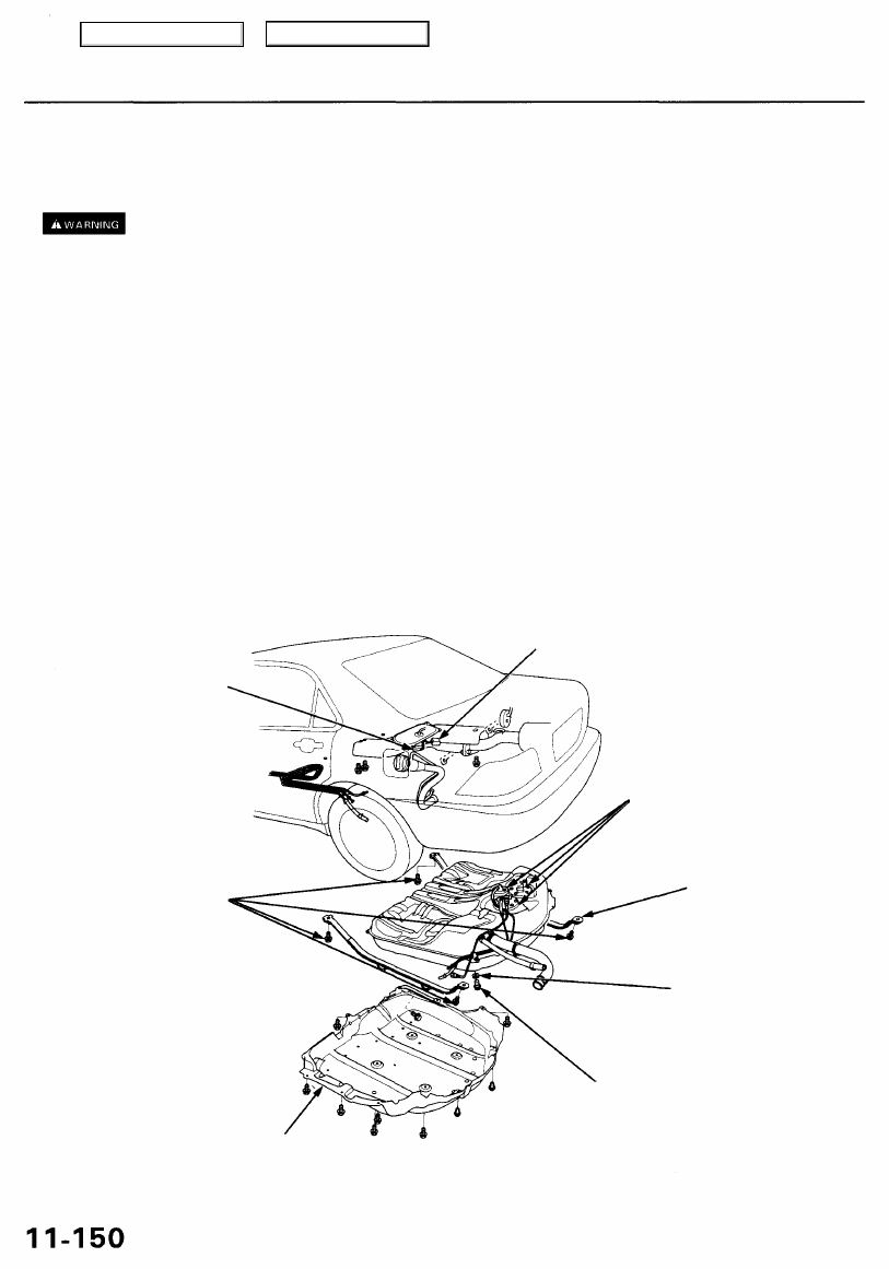
Fuel Tank
'96 - 99 models:
Replacement
Do not smoke while working on fuel system. Keep open flame away from your work area.
1. Relieve the fuel pressure (see page
).
2. Remove the seat cushion (see
).
3. Remove the access panel from the floor.
4. Disconnect the 2P and 3P connectors and harness clip.
5. Jack up the vehicle, and support it with jackstands.
6. Disconnect the muffler mount.
7. Remove the heat shield.
8. Remove the fuel tank cover.
9. Remove the drain bolt, and drain the fuel into an approved container.
10. Disconnect the hoses (see page
). Slide back the clamps, then twist hoses as you pull, to avoid damaging them.
11. Place a jack, or other support, under the tank.
12. Remove the strap nuts, and let the straps fall free.
13. Remove the fuel tank.
If it sticks on the undercoat applied to its mount, carefully pry it off the mount.
14. Install the drain bolt with a new washer, then coat the drain bolt with Noxrust 124B. Allow the Noxrust to dry for 20
minutes.
15. Install the remaining parts in the reverse order of removal.
3P CONNECTOR
2P CONNECTOR
BASE GASKET
Replace.
38 N-m
(3.9 kgf-m,
28 Ibf-ft)
FUEL TANK
STRAP
WASHER
Replace.
DRAIN BOLT
49 N-m (5.0 kgf-m, 36 Ibf-ft)
FUEL TANK
COVER
Main Menu
Table of Contents
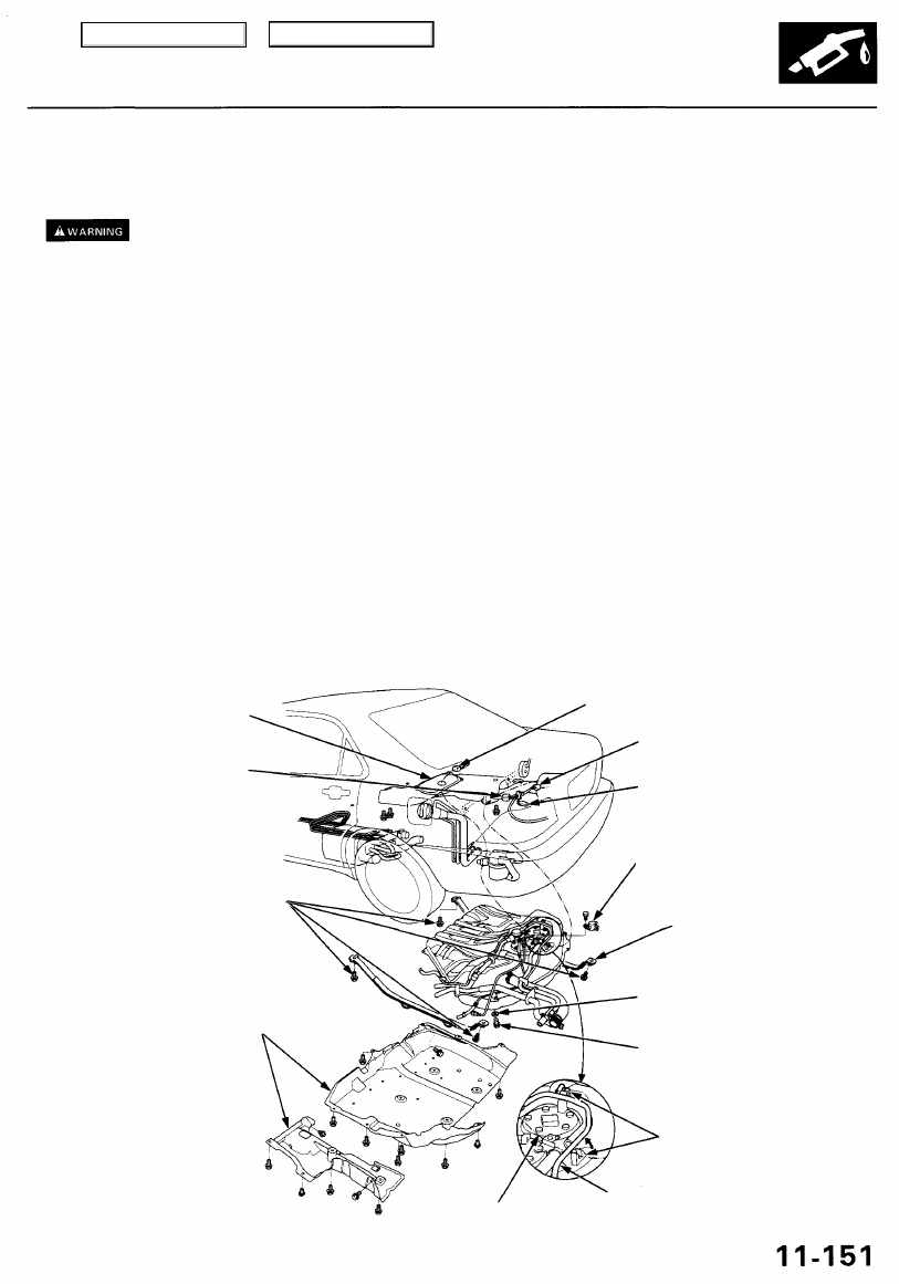
'00 - 01 models:
Replacement
Do not smoke while working on fuel system. Keep open flame away from your work area.
1. Relieve the fuel pressure (see page
).
2. Remove the seat cushion (see
).
3. Disconnect the 10P connector from the fuel unit wire harness.
4. Remove the access panel from the floor.
5. Disconnect the 2P and 3P connectors and harness clip.
6. Remove the Fuel Tank vapor recirculation valve mounting bolt and Fuel Tank vapor recirculation valve.
7. Remove the Vapor signal tube from the clips.
8. Remove the fuel unit wire harness from the access panel, and pass the Fuel Tank signal tube.
9. Jack up the vehicle, and support it with jackstands.
10. Disconnect the muffler mount.
11. Remove the heat shield.
12. Remove the fuel tank covers.
13. Remove the drain bolt, and drain the fuel into an approved container.
14. Disconnect the hoses (see page
). Slide back the clamps, then twist hoses as you pull, to avoid damaging them.
15. Place a jack, or other support, under the tank.
16. Remove the strap nuts, and let the straps fall free.
17. Remove the fuel tank.
If it sticks on the undercoat applied to its mount, carefully pry it off the mount.
18. Install the drain bolt with a new washer, then coat the drain bolt with Noxrust 124B. Allow the Noxrust to dry for 20
minutes.
19. Install the remaining parts in the reverse order of removal.
ACCESS
PANEL
3P CONNECTOR
FUEL UNIT
WIRE HARNESS
38 N-m
(3.9 kgf-m,
28 Ibf-ft)
FUEL TANK
COVERS
WIRE HARNESS
10P CONNECTOR
2P CONNECTOR
FUEL TANK VAPOR
RECIRCULATION
VALVE
FUEL TANK
STRAP
CLIPS
FUEL TANK VAPOR SIGNAL
TUBE
WASHER
Replace.
DRAIN BOLT
49 N-m (5.0 kgf-m, 36 Ibf-ft)
Main Menu
Table of Contents
Нет комментариевНе стесняйтесь поделиться с нами вашим ценным мнением.
Текст