Acura RL (1996-2004 year). Manual — part 367

•: with TCS
*1: with VSA
": with TCS
"1: with VSA
*: '00 - 01 models
*: with TCS
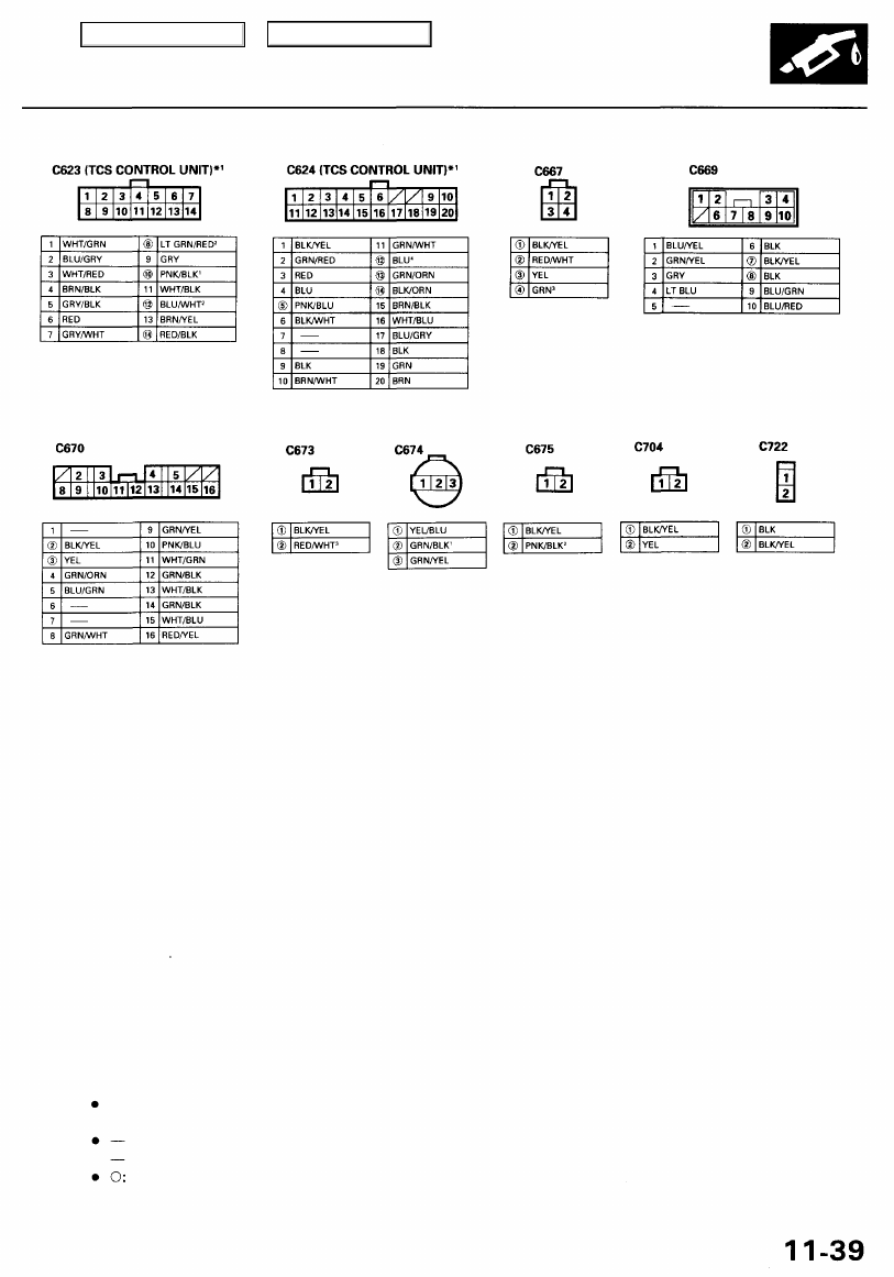
NOTE:
Different wires with the same color have been given a number suffix to distinguish them (for example, YEL/BLK
1
and YEL/BLK
2
are not the same).
Connector with male terminals (double outline): View from terminal side
Connector with female terminals (single outline): View from wire side
Related to Fuel and Emissions System.
Main Menu
Table of Contents
System Description
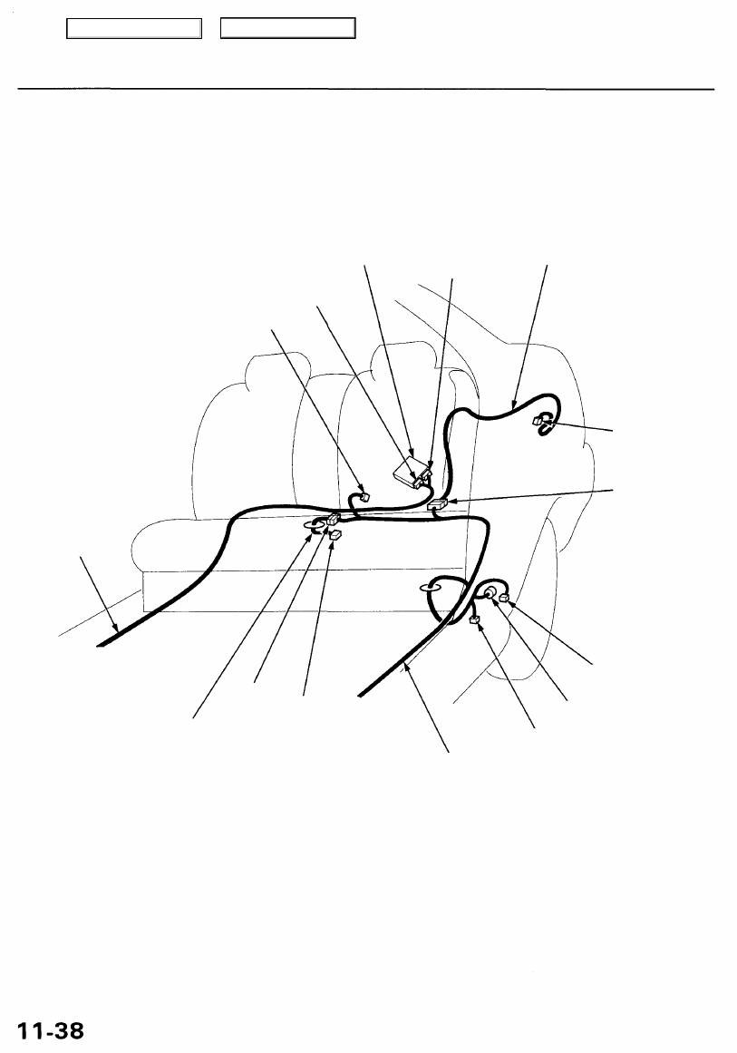
System Connectors [Dash and Floor] (cont'd)
TCS CONTROL UNIT*
1
C624
*
1
REAR
WIRE HARNESS
C667
C704
RIGHT
SIDE WIRE
HARNESS
C675
*
2
FUEL UNIT
WIRE HARNESS
LEFT SIDE WIRE
HARNESS
*1: '96 - 99 models
*2: '00 - 01 models
C669
C721
C722
C673*
2
C674
*
2
C670
C701
C623
*
1
Main Menu
Table of Contents
*1: '96 - 99 models
*2: '00 - 01 models
NOTE:
Different wires with the same color have been given a number suffix to distinguish them (for example, YEL/BLK
1
and YEL/BLK
2
are not the same).
Connector with male terminals (double outline): View from terminal side
Connector with female terminals (single outline): View from wire side
Related to Fuel and Emissions System.
Main Menu
Table of Contents
Troubleshooting
Troubleshooting Procedures
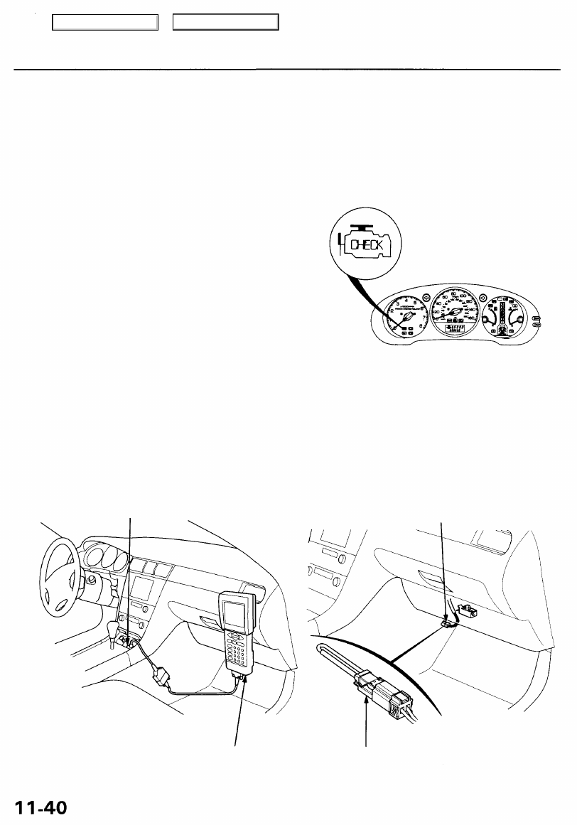
I. How To Begin Troubleshooting
When the Malfunction Indicator Lamp (MIL) has been reported on, or there is a driveability problem, use the appropri-
ate procedure below to diagnose and repair the problem.
A. When the MIL has come on:
1. Connect the Honda PGM Tester or an OBD II scan tool to the Data Link Connector (DLC) located on the center con-
sole behind the ashtray.
MALFUNCTION
INDICATOR
LAMP
(MIL)
2. Turn the ignition switch ON (II).
3. Check the Diagnostic Trouble Code (DTC) and note
it. Also check and note the freeze frame data.
Refer to the DTC Chart (see page
) and begin
troubleshooting.
NOTE:
• See the OBD II scan tool or Honda PGM Tester user's manuals for specific operating instructions.
• The scan tool or tester can read the DTC, freeze frame data, current data, and other Powertrain Control Module
(PCM) data.
• Freeze frame data indicates the engine conditions when the first malfunction, misfire or fuel trim malfunction was
detected. It can be useful information when troubleshooting.
B. When the MIL has not come on, but there is a driveability problem, refer to the Symptom Chart on page
C. DTCs will be indicated by the blinking of the MIL with the SCS service connector connected.
Connect the SCS service connector to Service Check Connector as shown. (The 2P Service Check Connector is
located under the dash on the passenger's side of the vehicle.) Turn the ignition switch ON (II).
SERVICE CHECK
CONNECTOR
DATA LINK CONNECTOR
SCS SERVICE CONNECTOR
HONDA PGM TESTER or
OBD II SCAN TOOL
Main Menu
Table of Contents
Нет комментариевНе стесняйтесь поделиться с нами вашим ценным мнением.
Текст