Acura RL (1996-2004 year). Manual — part 520
Modulator Unit
ABS Control Unit
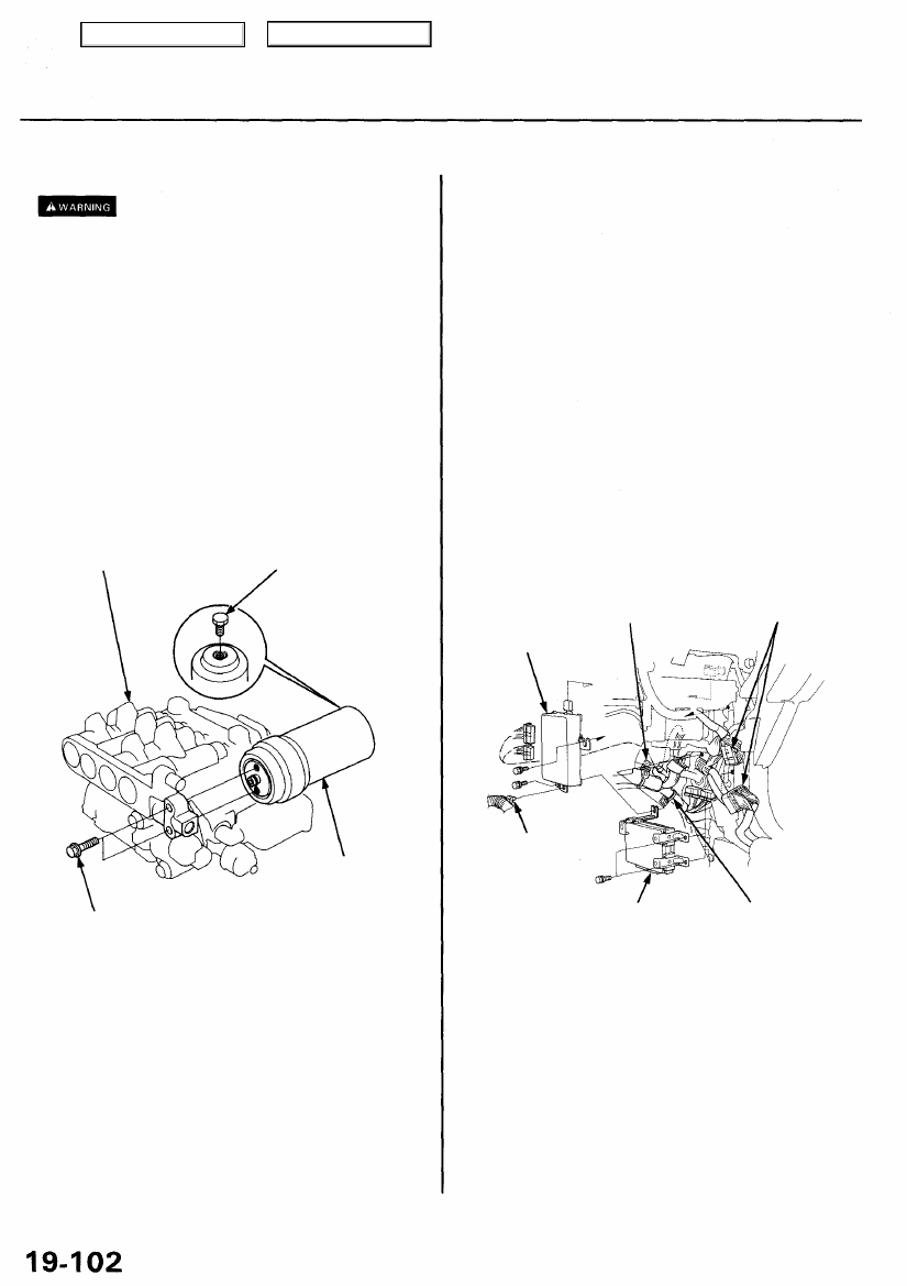
Accumulator Replacement and
Disposal
• The modulator unit contains high-pressure brake fluid.
Be sure to relieve system pressure before removing
the accumulator.
• The accumulator contains high-pressure nitrogen
gas. Do not puncture, expose to flame, weld, drop or
apply impact to the accumulator. The modulator unit
may explode and severe personal injury may result.
1. Relieve system pressure (see page
).
2. Remove the modulator unit (see page
).
3. Remove the relief plug slowly.
NOTE: When you loosening the relief plug about
one turn, you will hear the gas escaping.
4. Replace the accumulator.
MODULATOR UNIT
RELIEF PLUG
Removal/Installation
1. Remove the glove box.
2. Remove the glove box back cover.
3. Remove the right front door trim.
4. Remove the right kick panel.
5. Turn up the floor mat.
6. Remove the PCM cover.
7. Remove the connectors inside of the right kick panel.
8. Remove the harness clip A from the ABS control
unit, then remove the bolt at lower side of the ABS
control unit.
9. Remove the multiplex control unit (passenger's).
10. Remove the harness clip B and C.
11. Remove the bolt at the rear of the ABS control unit,
then pull out the ABS control unit.
NOTE: Check the ABS control unit after connecting
the connectors at inside of the right kick panel.
CONNECTORS
(Inside the
right kick panel.)
HARNESS
CLIP A
MULTIPLEX CONTROL HARNESS CLIP C
UNIT (PASSENGER'S)
12. Install the ABS control unit in the reverse order of
removal.
13. After installation, perform ABS function test (see
5. Perform modulator unit installation (see page
).
9.8 N-m (1.0 kgf-m, 7 Ibf-ft)
ACCUMULATOR
Replace.
ABS CONTROL UNIT
HARNESS CLIP B
Main Menu
Table of Contents
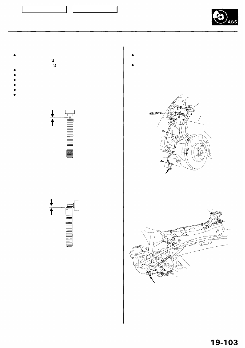
Pulsers/Wheel Sensor
Inspection
Inspection points:
Resistance
Front: 700-1,100
Rear: 1,400-2,000
Open in the wires
Short to body ground in the wires
Short the wire to other one
Installation
Chipped pulser
Air gap: 0.4 - 1.0 mm (0.02 - 0.04 in)
Front
Rear
Remove the rear brake disc to inspect the rear wheel
sensor air grip.
Wheel Sensor Replacement
NOTE:
Be careful when installing the sensors to avoid twist-
ing the wires.
The torque value of the bolts is at 9.8 N-m (1.0 kgf-m,
7 Ibf-ft).
Front
FRONT WHEEL SENSOR
Rear
REAR WHEEL SENSOR
Main Menu
Table of Contents
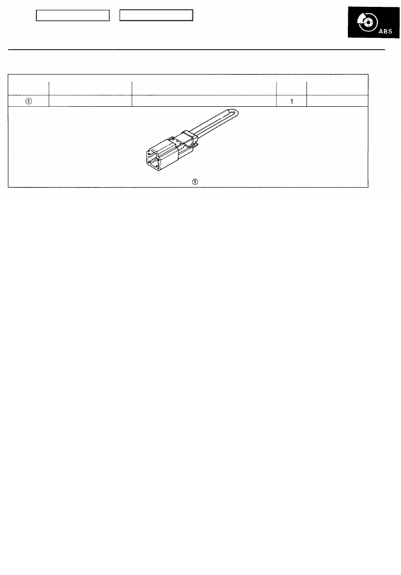
Special Tools
Ref. No.
Tool Number
Description
Qty
Page Reference
07PAZ-0010100 SCS Service Connector
Main Menu
Table of Contents
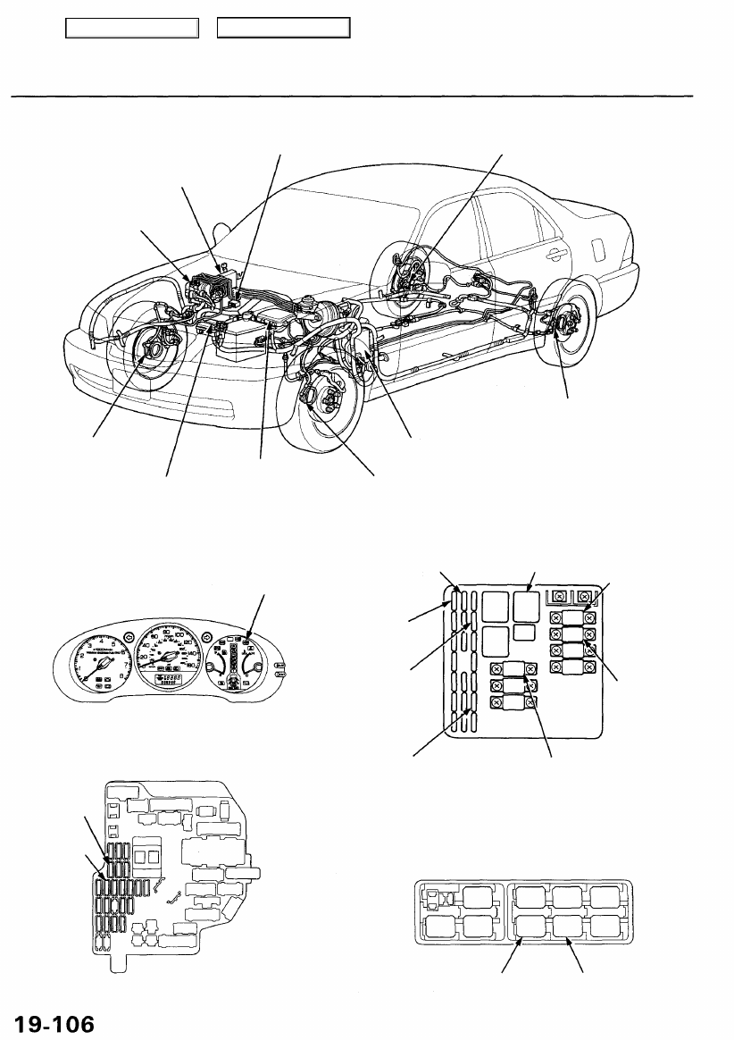
Component Locations
SERVICE CHECK CONNECTOR (2P)
RIGHT-REAR WHEEL SENSOR
ABS CONTROL UNIT
MODULATOR UNIT
LEFT-REAR
WHEEL SENSOR
RIGHT-FRONT
WHEEL SENSOR
UNDER-HOOD RELAY BOX C
UNDER-DASH FUSE/RELAY BOX
LEFT-FRONT WHEEL SENSOR
GAUGE ASSEMBLY
UNDER-HOOD FUSE/RELAY BOX
ABS INDICATOR
UNDER-DASH FUSE/RELAY BOX
R/C MIRROR
(7.5 A) FUSE
METER
(7.5 A) FUSE
STOP/HORN
(15 A) FUSE
ABS UNIT
(7.5 A) FUSE
ABS
(20 A) FUSE
ABS PUMP
MOTOR RELAY
METER
(15 A) FUSE
BATTERY
(120 A) FUSE
ABS MOTOR
(40 A) FUSE
IG SW (50 A) FUSE
UNDER-HOOD RELAY BOX C
GAUGE RELAY
FAIL-SAFE RELAY
UNDER-HOOD FUSE/RELAY BOX
Main Menu
Table of Contents
Нет комментариевНе стесняйтесь поделиться с нами вашим ценным мнением.
Текст