Acura RL (1996-2004 year). Manual — part 84
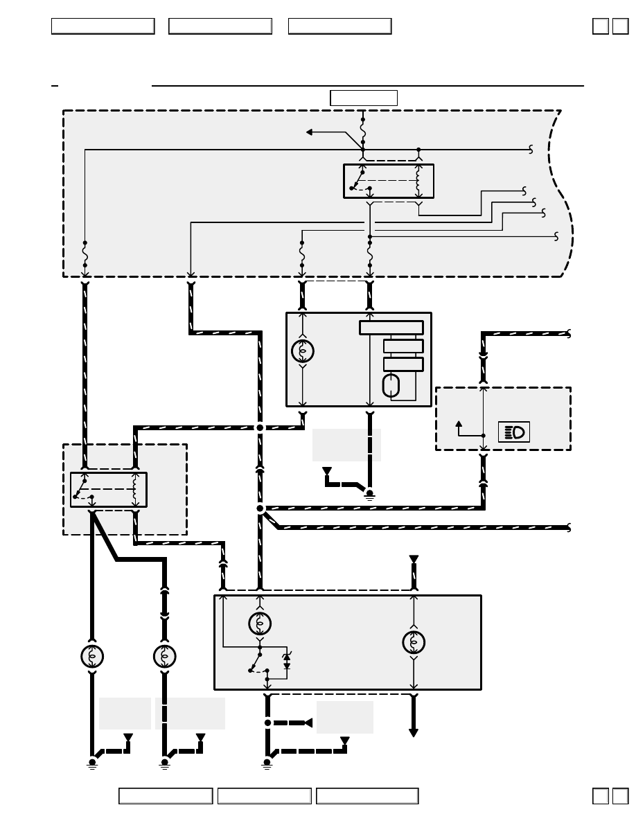
110-14
Headlights and Fog Lights
See Ground
Distribution,
page 14-2.
C328
C305
HEAD-
LIGHT
LOW
BEAM
RELAY
BATTERY
120A
ON
INDICATOR
LIGHT
‘99-’04 USA
2
1
RED/BLU
2
RED/YEL
BLK
8
LEFT
HEADLIGHT
1= Low
2= High
See Ground
Distribution,
page 14-12.
BLK
BLK
FOG
LIGHT
SWITCH
LIGHT
OFF
ON
FOG LIGHT
SWITCH
PHOTO 159
VIEW 125
(Navigation)
RED
RED/BLU
RED/BLK
RED/BLU
C325
1
11
FOG
LIGHT
RELAY
BLU/
RED
8
FR FOG
20A
5
2
1
BLK
3
2
LT GRN
LEFT
FOG
LIGHT
BLK
3
2
RIGHT
FOG
LIGHT
See Ground
Distribution,
page 14-7.
G301
G201
C202
8
C325
3
LT GRN
LT GRN
LT GRN
RED/
BLU
3
BRN/YEL
BRN/YEL
C307
2
UNDER-
HOOD
RELAY
BOX C
RED/BLU
See Power
Distribution,
page 10-1.
L
20A
HEADLIGHT
LOW
*
= Navigation
L
10A
HEADLIGHT
HIGH
3
RED/YEL
Inverter
Igniter
2
1
3
C306
See Ground
Distribution,
page 14-6.
BLK
G301
ASSEMBLY
(’99-’03)
B
B
HIGH BEAM
INDICATOR
LIGHT
20
RED/BLU
16
C430
10
RED/BLU
RED/GRN
C430
8
4
)
(
*
5)
2
)
(
*
3)
3
)
(
*
4)
1
)
(
*
2)
)
(
*
6)
RED/BLU
B
A
A
B
RED/
BLU
BLK
G402
HOT AT ALL TIMES
See
Gauge
Assembly
2004 American Honda Motor Co., Inc.
▲
▲
+
–
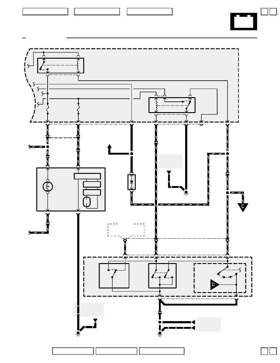
110-15
Headlights and Fog Lights
1
‘99-’04 USA
5
7
3
C301
UNDER-
HOOD
FUSE/
RELAY
BOX
COMBINATION
LIGHT SWITCH
3
2
BLU/RED
5
8
3
BLU/RED
Dimmer
Switch
OFF
ON
OFF
ON
LO
HI
OFF
PARK
C326
12
BLU/RED
BLU/RED
See Ground
Distribution,
page 14-7.
G301
BLK
C326
13
RED/BLU
RED/BLU
RED/BLU
AUTO
BLK
9
G401
See Ground
Distribution,
page 14-10.
BLK
BLK
C415
4
BLK
2
BRN/
WHT
1
BLK
DIMMER
RELAY
R
20A
HEAD-
LIGHT
LOW
R
10A
HEAD-
LIGHT
HIGH
From
page
110-16.
To page
110-16.
BLU/RED
2
2
RED/GRN
BLK
6
RIGHT
HEAD-
LIGHT
1= LOW
2= HIGH
3
RED/BLK
Inverter
Igniter
2
1
9
7
C306
C305
(Not
used)
HEAD-
LIGHT
DIODE
PNK
PNK
BLU/RED
C415
6
2
C326
C201
RED/BLK
RED/BLK
See Ground
Distribution,
page. 14-2.
BLK
G201
3
RED/BLU
6
BLU/
RED
PNK
HEADLIGHT
HIGH BEAM
RELAY
5
RED/GRN
16
RED/
GRN
C202
C202
2
1
B
A
B
A
(Not used)
Flash-
to-
pass
Switch
’99-’03
2004 American Honda Motor Co., Inc.
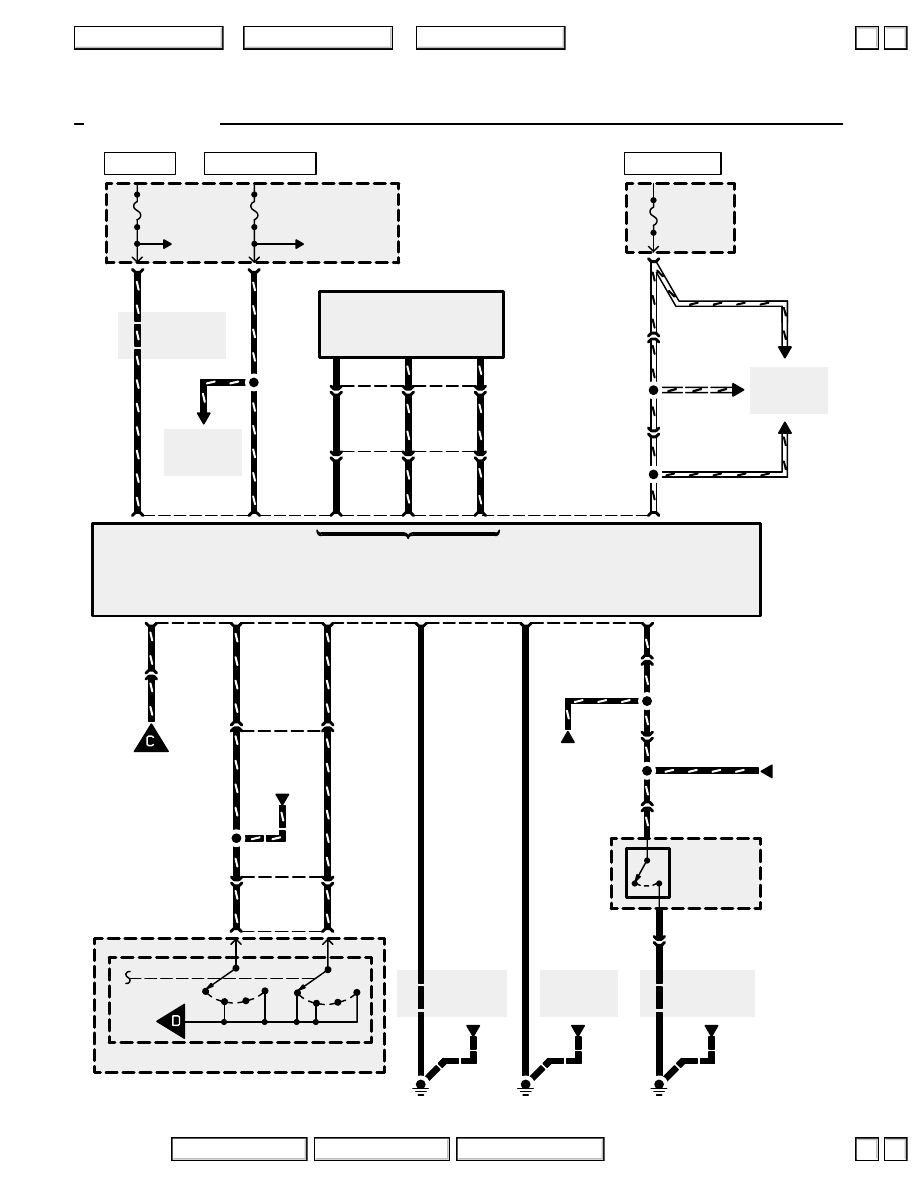
110-16
Headlights and Fog Lights
(
**
9)
4
See Power
Distribution,
page 10-7.
See Ground
Distribution,
page 14-5.
YEL/BLK
UNDER-DASH
FUSE/RELAY
BOX
See Power
Distribution,
page 10-7.
R/C MIRROR
7.5A
ECU
20A
UNDER-HOOD
FUSE/RELAY
BOX
BACK UP
RADIO
7.5A
C403
18
C651
7
BLK/YEL
3
AUTOMATIC
LIGHTING
CONTROL
UNIT
2
10
C307
7
Ignition
input
9
8
WHT/YEL
‘99-’04 USA
See Power
Distribution,
page 10-9.
BLK/YEL
WHT/YEL
12
C409
4
C327
WHT/YEL
See Power
Distribution,
page 10-15.
WHT/YEL
WHT/YEL
WHT/YEL
WHT/YEL
See Power
Distribution,
page 10-9.
See Ground
Distribution,
page 14-4.
BLK
G251
BLK
G651
BLK
See Ground
Distribution,
page 14-16.
Ignition
input
Battery
input
Ground
Ground
12
GRN/BLU
DRIVER’S
DOOR
LATCH
GRN/BLU
BLK
G251
8
C744
BLK
Door Switch
Closed with
door open.
3
C744
GRN/BLU
10
C412
GRN/BLU
GRN/BLU
BLK
GRN/BLU
Driver’s door
switch input
COMBINATION
LIGHT SWITCH
Headlight Switch
6
7
RED/GRN
HEAD
OFF
PARK
RED/GRN
AUTO
5
6
GRN/YEL
HEAD
OFF
PARK
AUTO
14
RED/GRN
5
BLU/RED
BLU/RED
C410
9
(
**
8)
5
13
GRN/YEL
GRN/YEL
C409
3
C415
Headlight
relay
control
Taillight
relay
control
Headlight
switch input
To page
110-15.
RED/GRN
7
AUTOMATIC
LIGHTING
SENSOR
5
3
BRN
BRN
4
2
YEL/GRN
YEL/GRN
1
C504
6
1
RED/YEL
RED/YEL
7
C511
Automatic lighting
sensor input
From page
110-15.
GRN/BLU
C409
(C414
**
)
GRN/
BLU
BRN
YEL/GRN
RED/YEL
**
= ’02-’04 USA
YEL/BLK
HOT IN ON OR START
HOT IN ON
HOT AT ALL TIMES
2004 American Honda Motor Co., Inc.
▼
▼
+
–
110-17
Headlights and Fog Lights
How the Circuit Works
WARNING
A transient high tension (25,000 V) occurs at the
bulb sockets of the high intensity discharge
(HID) lamps when the combination light switch
is turned ON. It may cause serious electrical
shock or electrocution if you do not observe the
cautions below.
CAUTION
•
Never turn on the combination light switch
before fitting the HID bulbs to their bulb
sockets and completing the reassembly of
the headlight assembly.
•
Do not service the headlight assembly in wet
conditions, such as rain or snow, near a
sprinkler system, or when your hands are
wet to prevent electrocution.
•
Do not touch the surface of the HID bulbs
with your bare hands and do not stain it with
any oils or fats.
•
Do not disassemble the inverter unit and the
igniter unit.
•
Do not turn on the HID bulb by using a power
source other than the battery mounted on the
vehicle.
Low Beams
The headlight low beam and high beam relays
receive battery voltage at all times. When you turn
the headlight switch to the HEAD position with the
dimmer switch in LOW, ground is applied through
the BLU/RED wire and lighting diode to the coils of
the headlight low beam and high beam relays. The
relays are then energized, applying battery voltage
to the left and right low and high beam headlights
through fuses 45, 46 and 48, 49 respectively. The
low beam bulbs come on because they are
individually grounded by G301 and G201. The high
beams and indicator remain off because their
ground path is interrupted by the deenergized
dimmer relay.
High Beams
When you pull the dimmer switch to HIGH with the
low beams already on, ground is applied to the
dimmer relay from the dimmer switch. This
energizes the dimmer relay, applying ground to the
high beam bulbs and high beam indicator, which
turns on the high beams and indicator light. The low
beams go off because their ground path is
interrupted by the activated dimmer relay.
Flash-to-Pass
When you hold the flash-to-pass switch in the ON
position, ground is applied through the BLU/RED
wire and lighting diode to the coils of the headlight
low beam and high beam relays and through the
RED/BLU wire to the coil of the dimmer relay. This
energizes the headlight low beam and high beam
relays, applying battery voltage to the low and high
beam bulbs and to the dimmer relay. As the high
beam bulbs receive battery voltage, the dimmer
relay is energized, applying ground to the high
beam bulbs and high beam indicator, which turns
on the high beams and indicator light. The low
beams go off because their ground path is
interrupted by the activated dimmer relay.
Automatic Lighting
When you move the headlight switch to the AUTO
position, the automatic lighting control unit will
automatically turn on the headlights.
The automatic lighting control unit receives battery
voltage through fuse 56 at all times and receives
battery voltage through fuse 20 with the ignition
switch in ON (ll) and START (lll). When the ignition
switch is turned to ON (ll), the automatic lighting
control unit receives an “ignition on” signal through
fuse 19. When the headlight switch is in the AUTO
position with the driver’s door closed, and if the
automatic lighting sensor detects low ambient light,
the automatic lighting control unit will apply ground
to the BLU/RED wire and lighting diode and ground
the headlight low beam and high beam relays. The
relays energize and cause the high or low beam
headlights to come on, depending on the position of
the dimmer switch. The headlights will operate as if
they had been turned on with the headlight switch.
When the driver’s door is open, ground is applied to
the automatic lighting control unit through the
GRN/BLU wire. When the control unit receives this
ground signal, it removes ground from the headlight
relay and causes the headlights to turn off. The
automatic lighting control unit will also turn off the
headlights if the ambient light levels rise to daylight
conditions or if the headlight switch is moved out of
the AUTO position.
Refer to the Service Manual (Section 23, Electrical) for
specific tests and troubleshooting procedures.
2004 American Honda Motor Co., Inc.
▲
▼
▲
▼
Нет комментариевНе стесняйтесь поделиться с нами вашим ценным мнением.
Текст