Acura RL (1996-2004 year). Manual — part 85
110-18
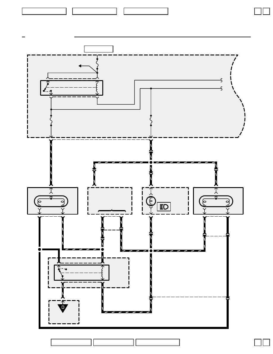
Headlights
C325
HEADLIGHT
RELAY
GAUGE
ASSEMBLY
B
C430
B
C430
HIGH BEAM
INDICATOR
LIGHT
See Power
Distribution,
page 10-1.
BATTERY
120A
8
20
8
RED/BLU
RED/GRN
10
LEFT
HEADLIGHT
ORN
1
3
2
RED/YEL
RED/BLU
16
UNDER-
HOOD
FUSE/
RELAY
BOX
C306
RIGHT
HEADLIGHT
RED/BLU
3
1
2
RED/GRN
ORN
DAYTIME
RUNNING
LIGHTS
CONTROL UNIT
11
1
10
RED/GRN
YEL/BLU
6
C305
6
DRL
output
High beam/
DRL mode
control
RED/GRN
YEL/BLU
To page
110-19.
‘96-‘98 Canada
R
15A
HEAD-
LIGHT
L
15A
HEAD-
LIGHT
RED/WHT
1
2
3
4
LOW
BEAM
CUT
RELAY
UNDER-
HOOD
RELAY
BOX A
C326
15
ORN
4
RED/BLU
RED/BLU
RED/BLU
C410
10
YEL/BLU
C326
5
RED/GRN
RED/GRN
RED/BLU
1
ORN
ORN
3
2
C202
YEL/BLU
ORN
RED/GRN
C410
12
C201
16
RED/GRN
18
YEL/BLU
YEL/BLU
LOW
HIGH
HIGH
LOW
HOT AT ALL TIMES
2004 American Honda Motor Co., Inc.
▲
▲
+
–
110-19
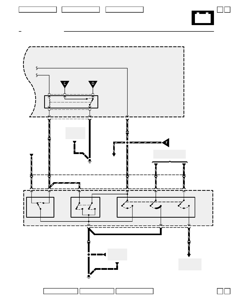
Headlights
‘96-‘98 Canada
DIMMER
RELAY
From page
110-20.
UNDER-HOOD
FUSE/RELAY
BOX
From page
110-18.
5
C305
7
7
C306
G301
3
2
BLU/RED
RED/BLU
1
BRN/
YEL
BLU/RED
BLU/RED
BLU/RED
From page
110-20.
See Headlight
Switch,
page 100-3.
Headlight
Switch
Flash-to-
pass
Switch
Dimmer
Switch
COMBINATION
LIGHT SWITCH
C415
6
G401
BLK
BLK
OFF
ON
OFF
ON
LO
HI
RED/GRN
C429
4
HEAD
OFF
PARK
HEAD
OFF
PARK
5
PNK/BLK
RED/BLK
9
HEAD
OFF
PARK
See Headlight Switch,
page 100-3.
2
8
BLU/RED
RED/BLU
10
BRN/
WHT
4
RED/GRN
5
RED/YEL
3
RED/BLU
BLK
BLK
11
9
PNK/BLK
7
C415
See Ground
Distribution,
page 14-7.
See Ground
Distribution,
page 14-8.
RED/BLU
C326
13
C326
12
BLU/RED
BLK
2004 American Honda Motor Co., Inc.
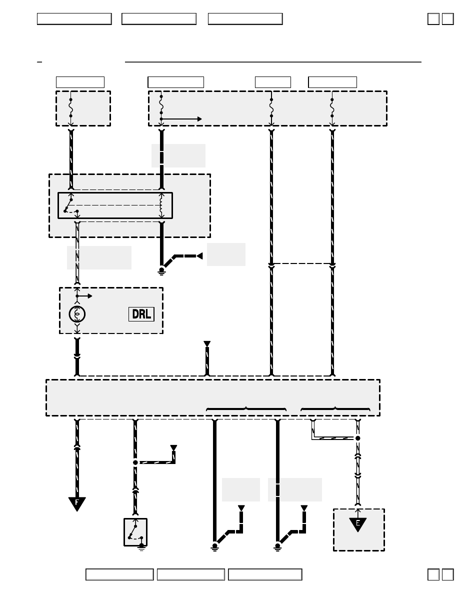
110-20
Headlights
3
)
(
*
5)
2
(
*
3)
5
)
1
GAUGE
RELAY
G301
See Ground
Distribution,
page 14-6.
See Power
Distribution,
page 10-10.
METER
7.5A
See Power
Distribution,
page 10-10.
YEL
YEL
C331
2
See Gauge
Assembly,
page 80 or 80-5.
A
22
B
17
WHT/RED
See Gauge Assembly
WHT/RED
DRL
INDICATOR
LIGHT
GAUGE
ASSEMBLY
C305
2
WHT/BLU
C326
17
WHT/BLU
5
METER
15A
RED/YEL
C307
1
UNDER-
HOOD
FUSE/
RELAY
BOX
UNDER-
DASH
FUSE/
RELAY
BOX
(RUNNING LIGHT)
7.5A
YEL/RED
C403
11
(RUNNING LIGHT)
10A
RED/BLU
C405
6
9
YEL
C504
7
YEL
See Ground
Distribution,
page 14-8.
G401
DRL indicator
light control
Headlight
ON input
To page
110-19.
UNDER-
HOOD
FUSE/
RELAY
BOX
UNDER-
HOOD
RELAY
BOX C
C410
11
WHT/BLU
WHT/BLU
3
WHT/BLU
DAYTIME
RUNNING
LIGHTS
CONTROL
UNIT
4
See Ground
Distribution,
page 14-16.
G651
7
BLK
BLK
BLK
Dimmer relay input
Ground
6
)
(’98 3)
C414
17
)
(’98 9)
C414
5
)
(’98 2)
GRN/WHT
GRN/WHT
6
See Brake
System
Indicator Light
PARKING
BRAKE SWITCH
Closed with
parking brake
applied.
YEL/RED
RED/BLU
Ignition
input
Battery
input
GRN/WHT
GRN/WHT
Parking
brake
input
C410
9
BLU/RED
8
BLU/RED
To page
110-19.
BLK
GRN/RED
Brake
indicator
control
See Brake
System
Indicator Light
13
12
2
‘96-‘98 Canada
*
=’98
HOT IN ON OR START
HOT IN ON
HOT AT ALL TIMES
HOT AT ALL TIMES
2004 American Honda Motor Co., Inc.
▼
▼
+
–
110-21
Headlights
How the Circuit Works
Daytime Running Lights
When you turn the ignition switch to ON (II) with the
parking brake released, the daytime running lights
control unit supplies about 6 volts to the RED/GRN
wire (cavity 10), about 12 volts to the YEL/BLU wire
(cavity 1), and ground to the RED/BLU wire (cavity
11). This provides about 6 volts to both high beam
headlights, causing them to come on at reduced
brightness. At the same time, about 12 volts
energizes the coil of the low beam cut relay,
removing the ground path to the low beams. If you
apply the parking brake, ground is applied to the
daytime running lights control unit at the GRN/WHT
wire. If the parking brake is applied before you turn
the ignition switch to ON (II), the daytime mode will
remain off until you release the parking brake. Once
the high beams are in the daytime mode, applying
the parking brake will not turn them off. When you
switch to low beam, high beam, or flash-to-pass
operation, ground is applied to the daytime running
lights control unit through the BLU/RED wire, and
the control unit then turns off the daytime running
lights mode.
Low Beams
The headlight relay receives battery voltage at all
times. When you turn the headlight switch to the
HEAD position with the dimmer switch in LOW,
ground is applied through the BLU/RED wire to the
coil of the headlight relay. This energizes the relay,
applying battery voltage to the left and right low
beam headlights through fuses 45 and 46. The low
beam bulbs come on because the opposite terminal
is tied to ground through the low beam cut relay and
dimmer relay.
High Beams
When you pull the dimmer switch to HIGH with the
low beams already on, ground is applied to the
dimmer relay from the dimmer switch. This
energizes the dimmer relay, applying ground
through the WHT/BLU wires to the daytime
running lights control unit. The control unit applies
ground through the RED/BLU (cavity 11) and
YEL/BLU (cavity 1) wires to the high beam bulbs
and high beam indicator, which turns on the high
beams and indicator light. The low beam headlights
go off because their ground path is interrupted by
the activated dimmer relay.
Flash-to-Pass
When you hold the flash-to-pass switch in the ON
position, ground is applied through the BLU/RED
wire to the coil of the headlight relay and through
the RED/BLU wire to the coil of the dimmer relay.
This energizes the headlight relay, applying battery
voltage to the low and high beam bulbs and to the
dimmer relay. As the high beam bulbs receive
battery voltage, the dimmer relay is energized,
applying ground through the WHT/BLU wires to the
daytime running lights control unit. The control unit
applies ground through the RED/BLU (cavity 11)
and YEL/BLU (cavity 1) wires to the high beam
bulbs and high beam indicator, which turns on the
high beams and indicator light. The low beams go
off because their ground path is interrupted by the
activated dimmer relay.
2004 American Honda Motor Co., Inc.
▲
▼
▲
▼
Нет комментариевНе стесняйтесь поделиться с нами вашим ценным мнением.
Текст