Acura RL (1996-2004 year). Manual — part 391
Fuel Supply System
System Description
The fuel supply system consists of a fuel tank, in-tank
high-pressure fuel pump, PGM-FI main relay, fuel filter,
fuel pressure regulator, fuel pressure regulator control
solenoid valve, injectors, and fuel delivery and return
lines. This system delivers pressure-regulated fuel to the
injectors and cuts the fuel delivery when the engine is
not running.
Fuel Pressure
Relieving
Before disconnecting fuel pipes or hoses, release pres-
sure from the system by loosening the service bolt on
top of the fuel filter.
SERVICE
BOLT
12 N-m
(1.2 kgf-m, 8.7 Ibf-ft)
FUEL
FILTER
SHOP TOWEL
NOTE:
• A fuel pressure gauge can be attached at the ser-
vice bolt hole.
• Always replace the washer between the service
bolt and the special banjo bolt whenever the ser-
vice bolt is loosened.
• Replace all washers whenever the bolts are
removed.
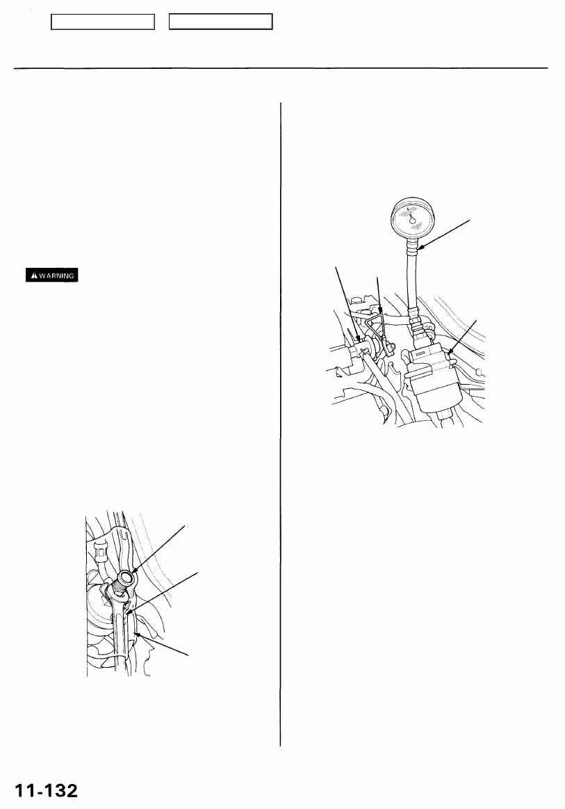
Inspection
1. Relieve fuel pressure.
2. Remove the service bolt on the fuel filter while hold-
ing the banjo bolt with another wrench. Attach the
special tool.
FUEL FILTER
3. Start the engine. Measure the fuel pressure with the
engine idling and the vacuum hose of the fuel pres-
sure regulator disconnected from the fuel pressure
regulator and pinched. If the engine will not start,
turn the ignition switch ON (II), wait for two sec-
onds, turn it OFF, then back on again and read the
fuel pressure.
Pressure should be:
299 - 348 kPa (3.05 - 3.55 kgf/cm
2
, 43.4 - 50.5 psi)
4. Reconnect vacuum hose to the fuel pressure regula-
tor.
Pressure should be:
240 - 289 kPa (2.45 - 2.95 kgf/cm
2
, 34.8 - 41.9 psi)
If the fuel pressure is not as specified, first check the
). If the fuel pump is OK,
check the following:
• If the fuel pressure is higher than specified,
inspect for:
— Pinched or clogged fuel return hose or line.
— Faulty fuel pressure regulator (see page
).
• If the fuel pressure is lower than specified, inspect
for:
— Clogged fuel filter.
— Faulty fuel pressure regulator (see page
).
— Fuel line leakage.
1. Make sure you have the anti-theft code for the
radio, then write down the frequencies for the
radio's preset buttons.
2. Disconnect the battery negative cable from the bat-
tery negative terminal.
3. Remove the fuel fill cap.
4. Use a box end wrench on the service bolt at the fuel
filter while holding the special banjo bolt with
another wrench.
5. Place a rag or shop towel over the service bolt.
6. Slowly loosen the service bolt one complete turn.
7. Reconnect the battery, enter the anti-theft code for
the radio, then enter the customer's radio station
presets.
• Do not smoke while working on the fuel system.
Keep open flames or sparks away from your work area.
• Be sure to relieve fuel pressure while the ignition
switch is off.
CLAMP
FUEL
PRESSURE
REGULATOR
FUEL
PRESSURE
GAUGE
Main Menu
Table of Contents
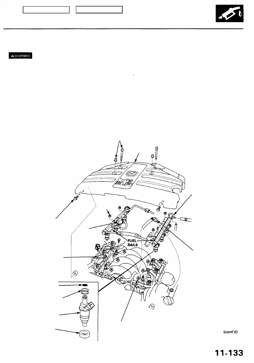
Injectors
Replacement
9.8 N-m
(1.0 kgf-m, 7.2 Ibf-ft)
Do not smoke when working on the fuel system. Keep open flames away from your work area.
1. Remove the strut bar.
2. Remove the engine cover.
3. Relieve fuel pressure (see page
).
4. Disconnect the connectors from the injectors.
5. Disconnect the PCV valve.
6. Disconnect the vacuum hose and fuel return hose from the fuel pressure regulator.
NOTE: Place a rag or shop towel over the hoses before disconnecting them.
7. Disconnect the fuel hose from the fuel rail.
8. Remove the vacuum pipe.
9. Loosen the retainer nuts on the fuel rail and harness holder.
10. Disconnect the 3P connector from the MAP sensor.
11. Disconnect the fuel rail.
12. Remove the injectors from the intake manifold.
HARNESS
HOLDER
SEAL
RING
Replace.
FUEL
PRESSURE
REGULATOR
INJECTOR
INSULATOR
PCV
VALVE
MAP
SENSOR
O-RING
Replace.
CUSHION
RING
Replace.
INJECTOR
12 N-m
(1.2 kgf-m,
8.7 Ibf-ft)
ENGINE
COVER
9.8 N-m
(1.0 kgf-m, 7.2 Ibf-ft)
Main Menu
Table of Contents
Fuel Supply System
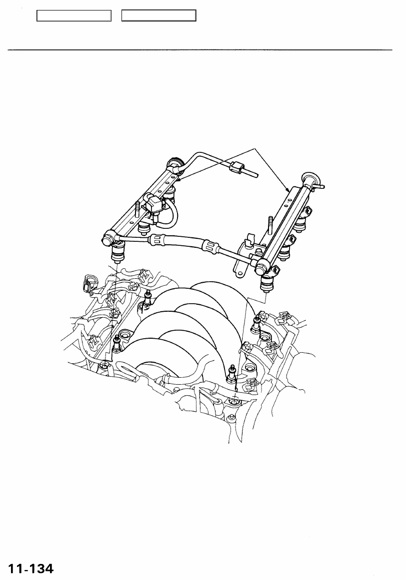
Injectors (cont'd)
13. Slide new cushion rings onto the injectors.
14. Coat new O-rings with clean engine oil, and put them on the injectors.
15. Insert the injectors into the fuel rail first.
16. Coat new seal rings with clean engine oil and press them into the intake manifold.
17. To prevent damage to the O-ring, install the injectors in the fuel rail first, then install them in the intake manifold.
FUEL
RAILS
18. Install and tighten the retainer nuts.
19. Connect the 3P connector to the MAP sensor.
20. Connect the fuel hose to the fuel rail.
21. Connect the vacuum pipe.
22. Connect the vacuum hose and fuel return hose to the fuel pressure regulator.
23. Install the connectors on the injectors.
24. Connect the PCV valve.
25. Turn the ignition switch ON (II), but do not operate the starter. After the fuel pump runs for approximately 2 seconds,
the fuel pressure in the fuel line rises. Repeat this two or three times, then check whether there is any fuel leakage.
26. Install the engine cover.
27. Install the strut bar.
Main Menu
Table of Contents
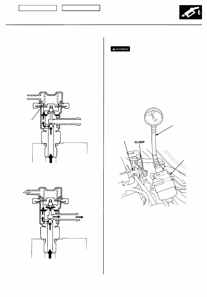
Fuel Pressure Regulator
Description
The fuel pressure regulator maintains a constant fuel
pressure to the injectors. When the difference between
the fuel pressure and manifold pressure exceeds 294
kPa (3.0 kgf/cm
2
, 43 psi), the diaphragm is pushed
upward, and the excess fuel is fed back into the fuel tank
through the return line.
DIAPHRAGM
FUEL INLET
OPEN:
To
INTAKE
MANIFOLD
FUEL
RETURN
FUEL INLET
Testing
Do not smoke during the test. Keep open
flames away from your work area.
1. Attach a fuel pressure gauge to the service port of
).
2. Start the engine.
Pressure should be:
299 - 348 kPa (3.05 - 3.55 kgf/cm
2
, 43-50 psi)
(with the fuel pressure regulator vacuum hose dis-
connected and pinched)
FUEL
PRESSURE
GAUGE
FUEL
PRESSURE
REGULATOR
FUEL FILTER
3. Reconnect the vacuum hose to the fuel pressure
regulator.
4. Check that the fuel pressure rises when the vacuum
hose from the fuel pressure regulator is disconnect-
ed again.
If the fuel pressure did not rise, replace the fuel pres-
sure regulator.
(cont'd)
CLOSED:
Main Menu
Table of Contents
Нет комментариевНе стесняйтесь поделиться с нами вашим ценным мнением.
Текст