Acura RL (1996-2004 year). Manual — part 458
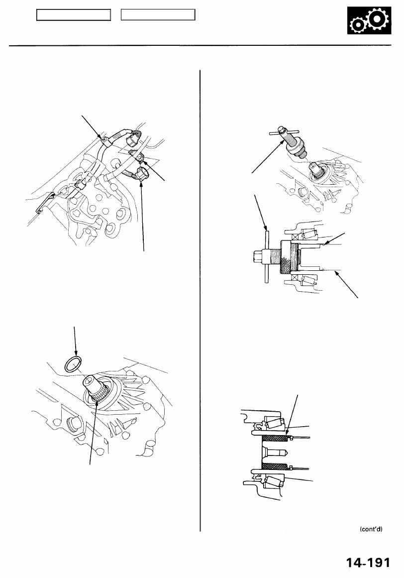
17. Connect the transmission range switch connector,
then install the clamp to the harness bracket.
CLAMP
HARNESS
BRACKET
TRANSMISSION RANGE
SWITCH CONNECTOR
18. Install a new set ring in the extension shaft groove.
SET RING
EXTENSION SHAFT
19. Install the extension shaft using the special tool as
shown.
NOTE: Push the extension shaft in the secondary
driven gear shaft until the extension shaft stops.
EXTENSION SHAFT
INSTALLER
SET RING
EXTENSION
SHAFT
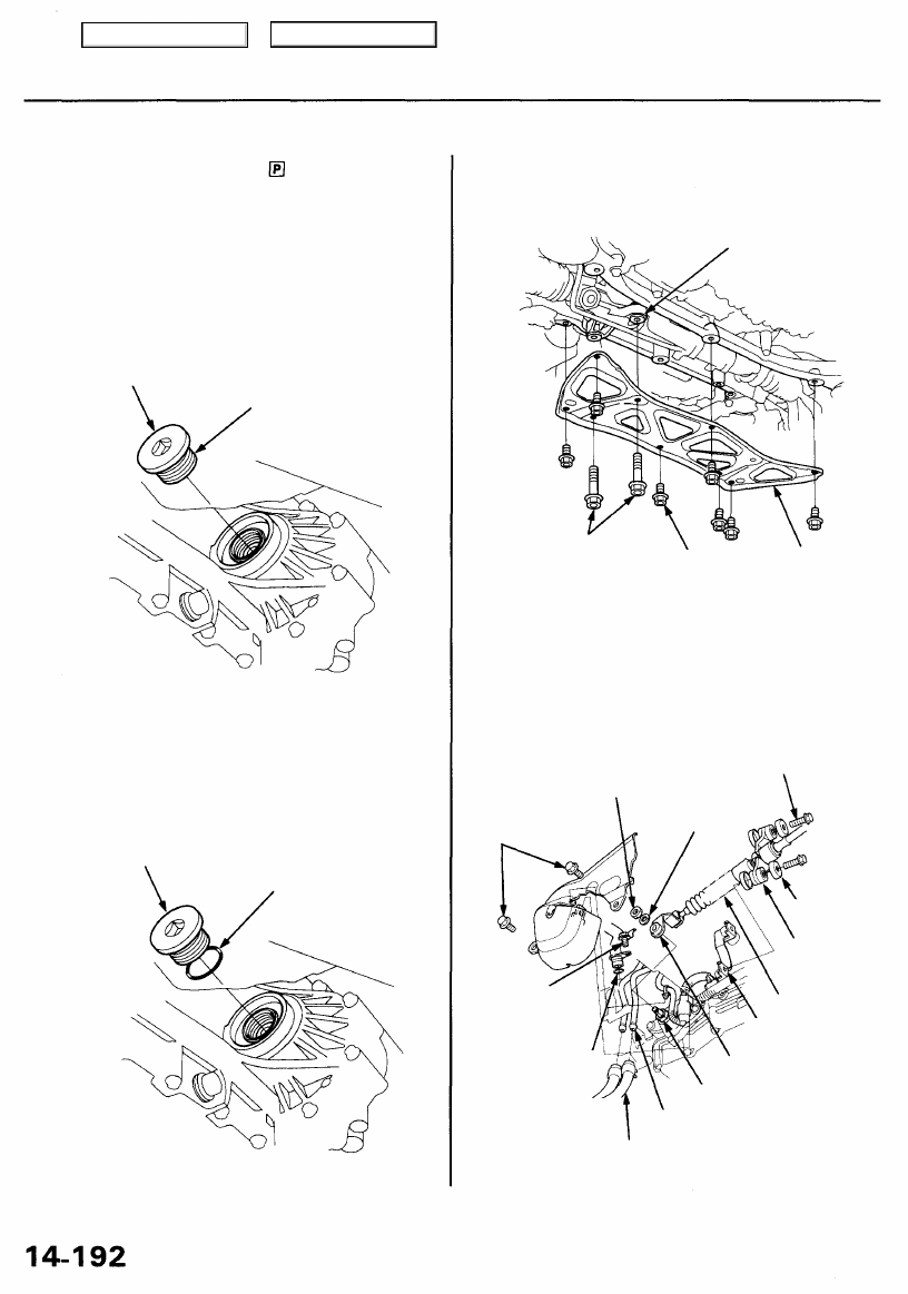
20. Remove the special tool.
21. Fill the opening between the secondary driven gear
shaft and the extension shaft with High Temp Urea
Grease (P/N 08798 - 9002), as shown.
SUPER HIGH TEMP UREA GREASE
(P/N 08798-9002)
12-14 g (0.4-0.5 oz)
Main Menu
Table of Contents
Transmission
Installation (cont'd)
22. Shift the transmission to the position by rotating
the control shaft.
23. Install the 36 mm sealing bolt.
'96 - '99 models:
Apply liquid gasket (P/N 08718 - 0001) to the 36 mm
sealing bolt threads, then install and tighten the
sealing bolt.
SEALING BOLT. 36 mm
78 N-m (8.0 kgf-m, 58 Ibf-ft)
Apply liquid gasket
to the threads.
'00-01 models:
Clean the opening bore of the secondary gear shaft.
Install the new O-ring on the sealing bolt, then
install them, and tighten the sealing bolt.
SEALING BOLT, 36 mm
78 N-m (8.0 kgf-m, 58 Ibf-ft)
O-RING
Replace.
24. Remove the steering gearbox mounting bolts, then
install the lower plate.
STEERING GEARBOX
STEERING GEARBOX
MOUNTING BOLTS 10 x 1.25 mm LOWER
10 x 1.25 mm 38 N-m PLATE
59 N-m (6.0 kgf-m, (3.9 kgf-m, 28 Ibf-ft)
43 Ibf-ft)
25. Install the control lever on the control shaft.
CAUTION: Take care not to bend the shift cable.
6 x 1.0 mm
12 N-m (1.2 kgf-m,
8.7 Ibf-ft)
WASHER
LOCKNUT
16 N-m (1.6 kgf-m,
12 Ibf-ft)
SPRING
WASHER
6 x 1.0 mm
12 N-m (1.2 kgf-m,
8.7 Ibf-ft)
SHIFT CABLE
HOLDER
SHIFT CABLE
SHIFT CABLE
HOLDER BASE
CONTROL LEVER
CONTROL SHAFT
ATF COOLER LINES
O-RING
Replace.
6 x 1.0 mm
12 N-m (1.2 kgf-m,
8.7 Ibf-ft)
ATF COOLER HOSES
Main Menu
Table of Contents
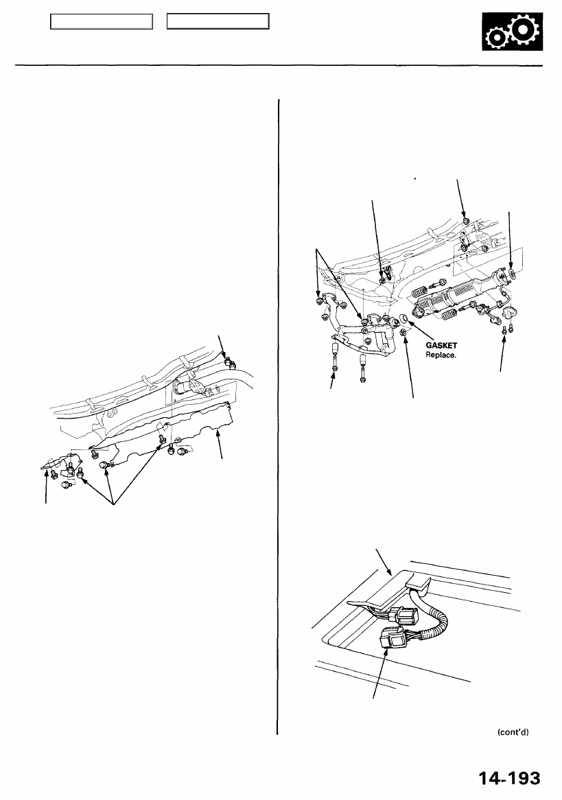
26. Install the shift cable holder on the shift cable holder
base.
27. Install the shift cable cover, and install the shift
solenoid valve/A/T clutch pressure control solenoid
valve harness connector and clamp on the shift
cable cover, then tighten the bolts.
28. Connect the ATF cooler hoses to the ATF cooler
).
29. Install the ATF dipstick tube with a new O-ring on the
torque converter housing.
30. Install the heat shields.
6 x 1.0 mm
9.8 N-m (1.0 kgf-m,
7.2 Ibf-ft)
HEAT SHIELD
HEAT
SHIELD
6 x 1.0 mm
9.8 N-m (1.0 kgf-m,
7.2 Ibf-ft)
31. Install the exhaust pipe A and the three way catalytic
converter, then install the transmission stop collars.
8 x 1.25 mm
22 N-m (2.2 kgf-m
16 Ibf-ft)
Replace.
10 x 1.25 mm
33 N-m (3.4 kgf-m,
25 Ibf-ft)
Replace.
10 x 1.25 mm
54 N-m (5.5 kgf-m,
40 Ibf-ft)
Replace.
GASKET
Replace.
10 x 1.25 mm
38 N-m (3.9 kgf-m,
28 Ibf-ft)
8 x 1.25 mm
22 N-m (2.2 kgf-m,
16 Ibf-ft)
Replace.
6 x 1.0 mm
9.8 N-m (1.0 kgf-m,
7.2 Ibf-ft)
32. Push the secondary HO2S connector into the vehi-
cle, then secure with the harness grommet.
33. Install the secondary HO2S harness cover.
34. Connect the secondary HO2S connector.
CARPET
HO2S (SENSOR 2) CONNECTOR
Main Menu
Table of Contents
Transmission
Installation (cont'd)
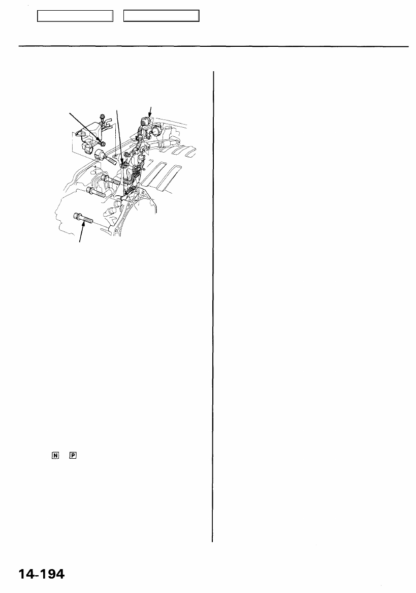
TRANSMISSION HOUSING
MOUNTING BOLTS
12 x 1.25 mm
64 N-m (6.5 kgf-m, 47 Ibf-ft)
36. Install the ATF dipstick tube bracket bolts.
37. Connect the transmission sub-harness connector.
38. Install the control box.
39. Install the strut brace.
40. Refill the transmission with the recommended ATF
(see page 1
).
41. Connect the battery positive (+) and negative (-)
cables to the battery terminals.
42. Set the parking brake. Start the engine, and shift the
transmission through all gears three times. Check
the shift lever operation and the A/T gear position
indicator operation.
43. Let the engine reach normal operating temperature
(the radiator fan comes on) with the transmission in
the or position, then turn it off and check ATF
level.
44. Road test as described on pages
thru
45. Enter the anti-theft radio code for the radio, then
enter the customer's radio station presets.
46. Memorize the engine idle speed signal in the PCM
).
35. Install the transmission housing mounting bolts.
TRANSMISSION
SUB-HARNESS
CONNECTOR
6 x 1.0 mm
12 N-m (1.2 kgf-m,
8.7 Ibf-ft)
6 x 1.0 mm
12 N-m (1.2 kgf-m,
8.7 Ibf-ft)
Main Menu
Table of Contents
Нет комментариевНе стесняйтесь поделиться с нами вашим ценным мнением.
Текст