Acura RL (1996-2004 year). Manual — part 225
8
2004 American Honda Motor Co., Inc.
How To Use This Manual
Symbols
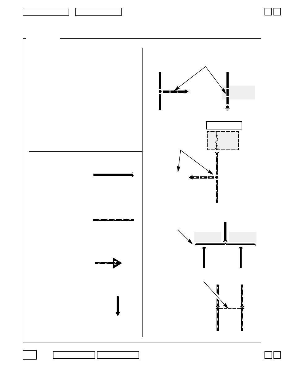
This circuit continues on
another page. (The arrow
shows direction of current
flow.) To follow the RED/
BLK wire in this example,
you would turn to page 23-5
and look for the “Z” arrow.
This broken line means
both terminals are in
connector C134.
Wire Color Abbreviations
BLK
YEL/RED
ORN
Name of Circuit
YEL/BLK
G101
See Ground
Distribution,
page 14-1.
FUSE 10
20A
UNDER-
DASH
FUSE/
YEL/BLK
C210
RED/BLU
RED/BLU
BLU/RED
C134
To C705
on
page 23-5.
RED/BLK
YEL
YEL
See
Stereo Sound
System, Clock
See
Cruise Control,
Gauges, Indicators
Wires
RELAY
BOX
ORN
Automatic
Transmission
Manual
Transmission
C309
C310
ORN
ORN
A broken line means this part of the circuit
is not shown; refer to the circuit listed for
the complete schematic.
Where separate wires
join, only the splice is
shown; for details on
the additional wiring,
refer to the circuits
listed.
Wire choices for options or
different models are labeled
and shown with a “choice”
bracket like this.
A wavy line at the end of
a wire means the wire is
broken by the binding of
the book or by a “choice”
bracket but continues on
the next page.
Wire insulation can be
one color, or one color
with another color stripe.
(The second color is
the stripe.)
This means the branch of the
wire connects to another
circuit. The arrow points to the
name of the circuit branch
where the wire continues.
2
5
The following abbreviations are used to
identify wire colors in the circuit schematics:
BLK
black
. . . . . . . . . . . . . . . . . . . . . . . . . . . . . . .
BLU
blue
. . . . . . . . . . . . . . . . . . . . . . . . . . . . . . .
BRN
brown
. . . . . . . . . . . . . . . . . . . . . . . . . . . . . .
GRN
green
. . . . . . . . . . . . . . . . . . . . . . . . . . . . . .
GRY
gray
. . . . . . . . . . . . . . . . . . . . . . . . . . . . . . .
LT BLU
light blue
. . . . . . . . . . . . . . . . . . . . . . . .
LT GRN
light green
. . . . . . . . . . . . . . . . . . . . . . .
ORN
orange
. . . . . . . . . . . . . . . . . . . . . . . . . . . . .
PNK
pink
. . . . . . . . . . . . . . . . . . . . . . . . . . . . . . . .
PUR
purple
. . . . . . . . . . . . . . . . . . . . . . . . . . . . . .
RED
red
. . . . . . . . . . . . . . . . . . . . . . . . . . . . . . . .
WHT
white
. . . . . . . . . . . . . . . . . . . . . . . . . . . . . .
YEL
yellow
. . . . . . . . . . . . . . . . . . . . . . . . . . . . . .
HOT AT ALL TIMES
▲
▲
9
2004 American Honda Motor Co., Inc.
How To Use This Manual
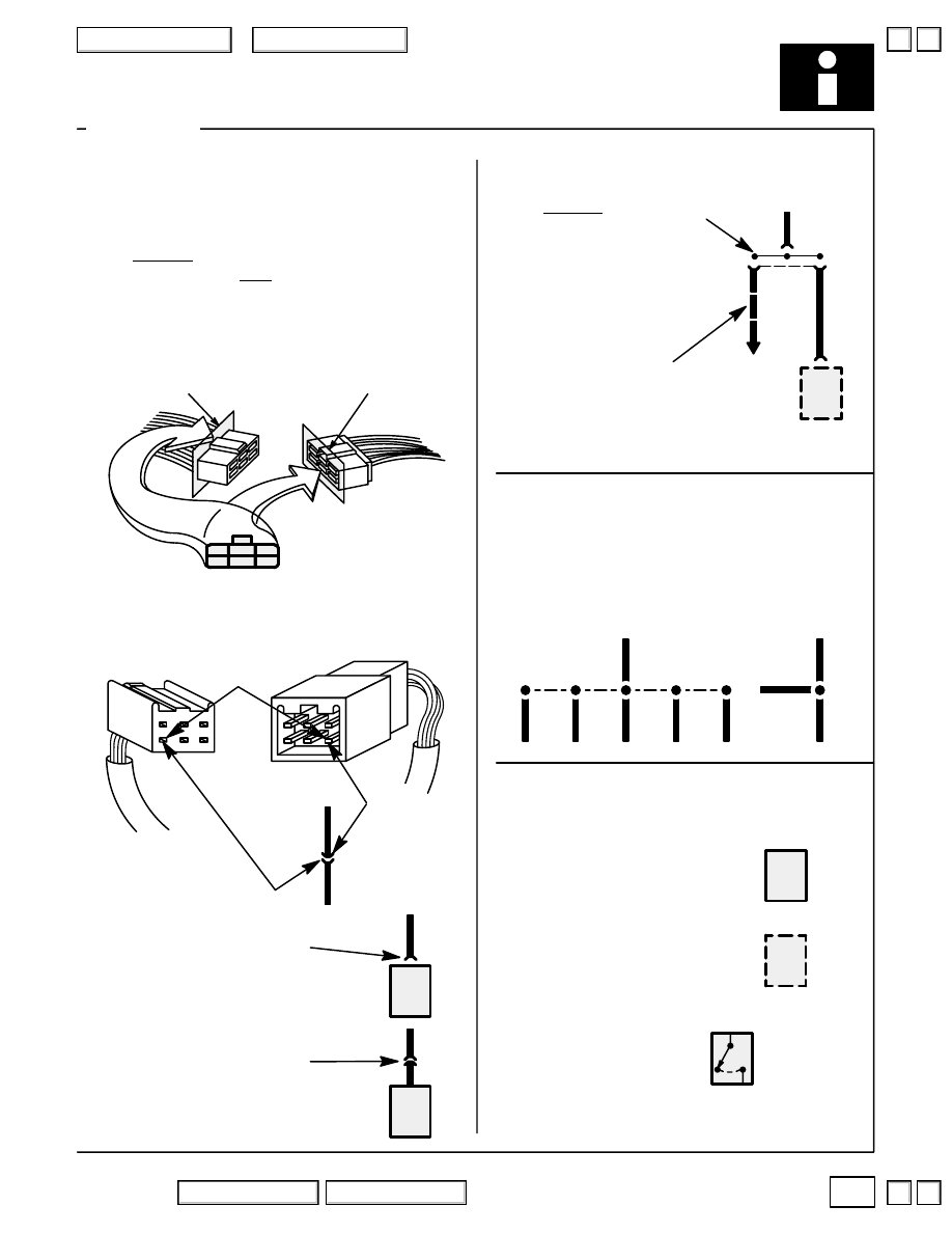
This means the connector
connects to a lead (pigtail)
wired directly to the com-
ponent.
This means the connector
connects directly to the
component.
The name of the
component appears next
to its upper right corner
followed by notes about
its function.
This symbol represents
one bus bar inside the cap
of a junction connector. A
junction connector cap
contains several bus bars,
but only the one affecting
that circuit will be shown.
The dots represent tabs
on the bus that the wire
terminals connect to.
Connectors – “C”
BLK
BLK
BLK
C103
GRY
GRY
Components
BRAKE
SWITCH
Closed with
pedal depressed.
Splices
Male
Terminal
6
Cavity/
Terminal 6
See Gauges
C103
The cavities (and wire terminals) in each
connector are numbered starting from the
upper left, looking at the male terminals from
the terminal side (or looking at the female
terminals from the wire side. Both views are in
the same direction so the numbers are the
same.) All actual cavities are numbered, even
if they have no wire terminals in them.
Female
Terminal
The connector cavity number is listed next to
each terminal on the circuit schematic. The
cavity/terminal shown below is #6.
Remaining wires to
the same bus are
represented by a
broken line.
Splices are shown as a dot. Their location
and the number of wires may vary depend-
ing on the harness manufacturer.
A solid border line means the
entire component is shown.
A broken border line indicates
that only part of the component
is shown.
Wire Side
of
Female Terminals
Terminal Side
of
Male Terminals
1
2
3
4
5
6
BLK
BLK
BLK
BLK
BLK
BLK
Symbols
10
2004 American Honda Motor Co., Inc.
How To Use This Manual
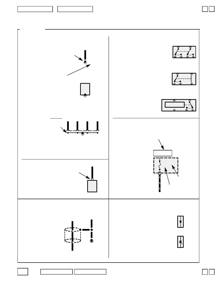
Each wire ground (G) is
numbered for reference.
This symbol means the end of
the wire is attached (grounded)
to the car frame or to a metal
part connected to the frame.
These switches move
together; the broken straight
line between them means they
are mechanically connected.
A Zener diode blocks reverse
current at normal voltages just like
a rectifier diode. At high voltages,
however, a Zener diode allows
current to flow in reverse.
T102
Fuses
Diodes
Identification
Current rating
FUSE 6
10A
GRN/BLK
A rectifier diode works like a one
way valve. It allows current to
flow only in the direction of the
arrow.
Each “T” terminal (ring type)
is numbered for reference and
location. A “T” terminal is
secured with a screw or bolt.
Terminals – “T”
Screw
terminal
G103
GRN
Shielding
Other types of switches are
controlled by a coil or a solid
state circuit. Unless otherwise
noted, all switches are shown
in their normal (rest) position,
with power off.
Solid-state
Ground – “G”
G101
G500
This symbol represents
the bus inside a ground
connector. The dots
represent tabs on the
bus that the wire
terminals connect to.
The ground symbol (large dot)
is the connection between the
bus and metal (grounded) part
of the car.
This ground symbol (dot
and 3 lines) overlapping the
component means the housing
of the component is grounded
to the car frame or to a metal
part connected to the frame.
This represents RFI
(Radio Frequency
Interference) shielding
around a wire. The
shielding is always
connected to ground.
This means power is supplied
when the ignition switch is in ON (II).
Symbols
Switches
HOT IN ON
▼
▼
2004 American Honda Motor Co., Inc.
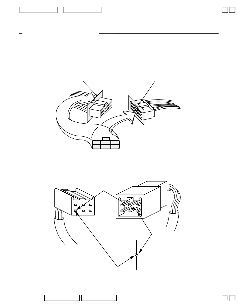
Connector Views
Male
Terminal
Cavity/
Terminal 6
The cavities (and wire terminals) in each connector are numbered starting from the upper left, looking
at the male terminals from the terminal side (or looking at the female terminals from the wire side. Both
views are in the same direction so the numbers are the same.) All actual cavities are numbered, even if
they have no wire terminals in them.
Female
Terminal
The connector cavity number is listed next to each terminal on the circuit schematic.
The cavity/terminal shown below is #6.
Wire Side
of
Female Terminals
Terminal Side
of
Male Terminals
1
2
3
4
5
6
6 C103
Terminal Numbering System
▲
▼
▲
▼
Нет комментариевНе стесняйтесь поделиться с нами вашим ценным мнением.
Текст