Acura RL (1996-2004 year). Manual — part 223
2
2004 American Honda Motor Co., Inc.
How To Use This Manual
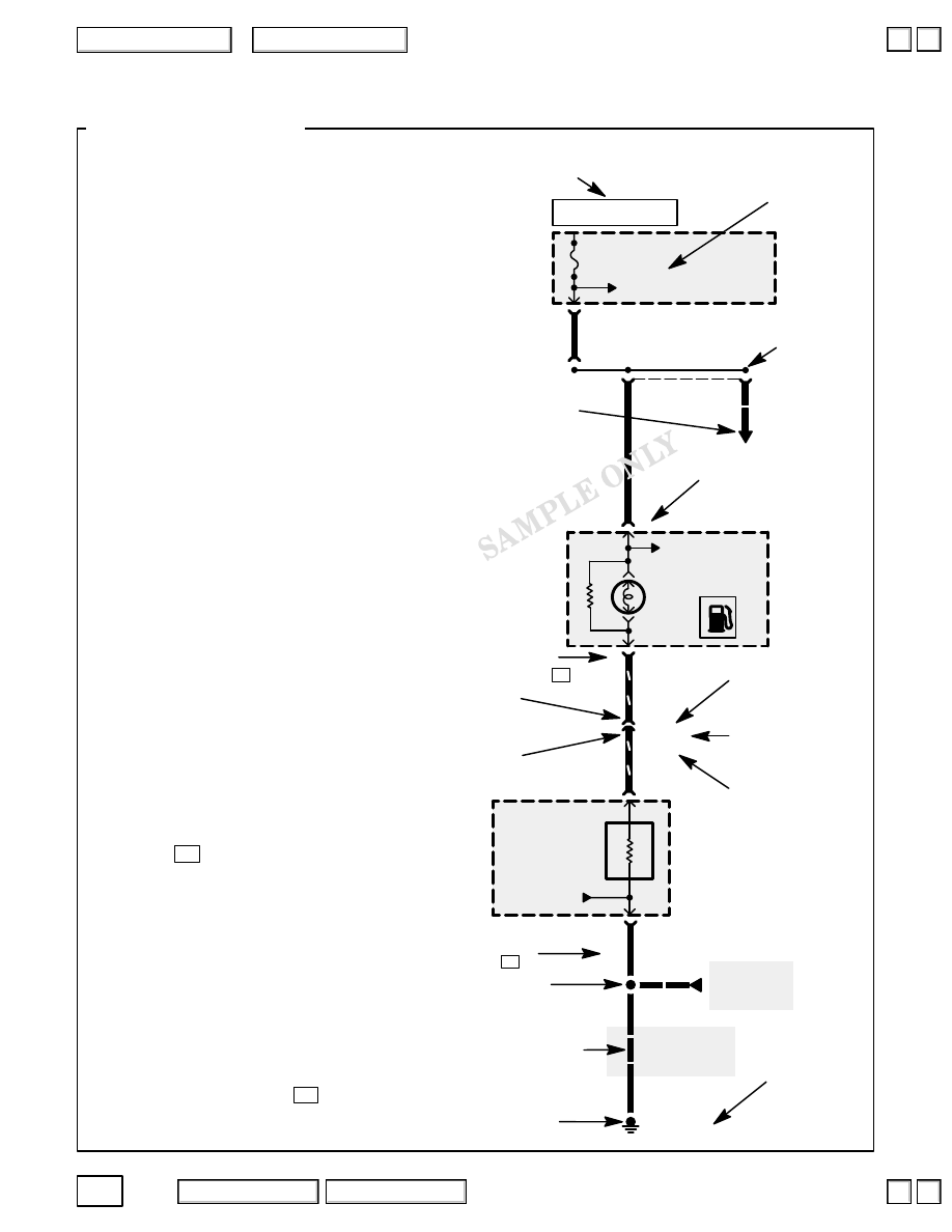
Each schematic represents one circuit. A
circuit’s wires and components are arranged to
show current flow, from power at the top of the
page, to ground, at the bottom.
Shared Circuits
Other circuits may share power or ground
terminals or wiring with the circuit shown. A
wire that connects one circuit to another, for
example, is cut short and has an arrowhead at
the end of it pointing in the direction of current
flow. Next to the arrowhead is the name of the
circuit or component which shares that wiring.
To quickly check shared wiring, check the
operation of a component it serves. If that
component works, you know the shared wiring
is OK.
Connectors
All in-line and junction connectors are
numbered (C725, C416, etc.). Component
connectors are not numbered but are identified
either by the name of the component if the
component only has one connector, or by a
capital letter (A, B, C, etc.) if the component
has
more than one
connector.
Below most connector numbers and
component names are PHOTO and VIEW
numbers. The PHOTO number
refers to a photo in the back of the book
that shows the connector’s location on the car.
The VIEW number refers to an illustration in
the back of the book that shows the connector
face, wire colors, connector cavity numbers,
and other details.
The connector cavity numbering sequence
begins at the top left corner of the connector
as seen from either of the viewpoints shown
on
.
Wires
Wires are identified by the abbreviated names
of their colors; the second color is the color of
the stripe. Wires are also identified by their
location in a connector. The number “2” next to
the male and female wire terminals at C416, for
example, means those terminals join in cavity 2
of connector C416.
Symbols
A complete description of schematic
symbols begins on
.
Capital letter means that
the gauge assembly has
more than one connector.
Circuit Schematics
See Ground
Distribution,
page 14-4.
FUEL
TANK
UNIT
PHOTO 48
UNDER-
DASH
FUSE/
RELAY
BOX
PHOTO 51
See Power Distribution,
page 10-3.
FUSE 13
10A
G301
PHOTO 21
PHOTO 25 (Coupe)
BLK
See Ground
Distribution,
page 14-4.
BLK
Thermistor
See Gauges
GAUGE
ASSEMBLY
VIEW 113
YEL
YEL
GRN/RED
GRN/RED
C416
PHOTO 52
VIEW 91
LOW FUEL
INDICATOR
LIGHT
See Indicators
C723
PHOTO 78
VIEW 6
A
A
BLK
C725
PHOTO 77
VIEW 75
2
1
2
1
2
“HOT” label tells you when
the ignition switch supplies
power to the fuse.
Arrow with note means
other circuits connect here.
Junction connector has one or
more bus bars in it; each connects
to two or more wire terminals.
Arrowhead means
wire connects to
another circuit;
it points in direction
of current flow.
Cavity number;
assigned as
shown on
.
Female
terminal
Male
terminal
Connector number;
index begins on
page 203.
Number of photo
in back of book
showing component
location on car.
Wire color code;
defined on
Splice
Broken wire means
part of the circuit is
not shown; look
elsewhere.
Ground
2
Number of connec-
tor view
in back of book
Variations
are indicated
by model.
HOT AT ALL TIMES
3
2004 American Honda Motor Co., Inc.
How To Use This Manual
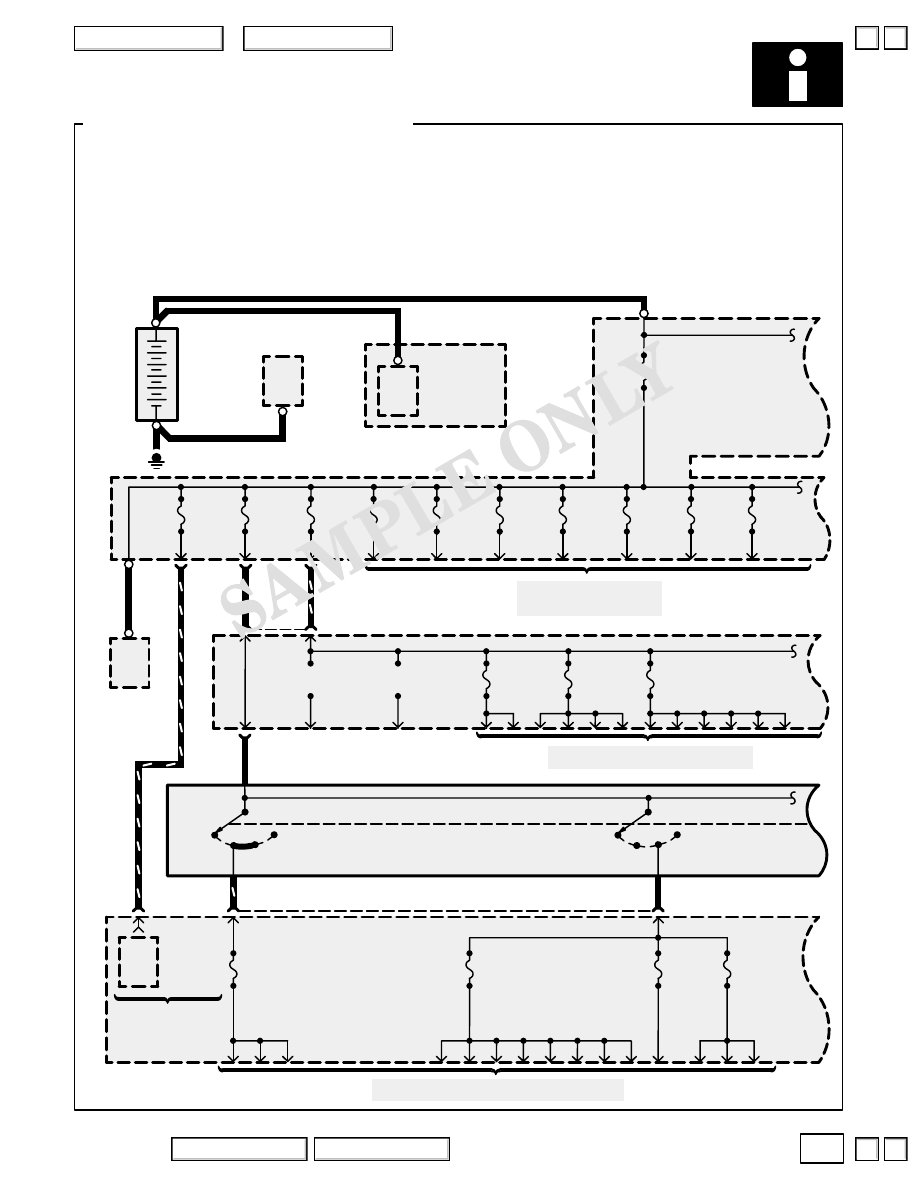
Power Distribution Schematics
Power Distribution schematics show how power is supplied from the positive battery terminal to
various circuits in the car. Refer to the Power Distribution section to get a more detailed picture
of how power is supplied to the circuit you’re working on.
From Battery to Ignition Switch, Fuses, and Relays
Individual circuit schematics begin with a fuse. The first half of Power Distribution, however,
shows the wiring “upstream” between the battery and the fuses.
C304
PHOTO 37
C307
PHOTO 37
VIEW 47
T101
PHOTO
34
FUSE 8
DR POWER SEAT
20A
See Power Distribution, page 10-2.
1
3
FUSE 9
(Not Used)
FUSE 6
ECU
20A
C329
PHOTO 76
+
–
BATTERY
CYLINDER
BLOCK
T2
T1
PHOTO 34
BLK
STARTER
Page 21
STARTER
SOLENOID
BLK
G1
PHOTO 29
BLK
T3
PHOTO 64
FUSE 31
BATTERY
120A
BLK
T102
ALTER-
NATOR
Page 22
PHOTO 29
FUSE 33
REAR
DE-
FROSTER
40A
FUSE 50
CON-
DENSER
FAN
20A
FUSE 52
POWER
SEAT AS
30A
FUSE 4
ACC
RADIO
10A
FUSE 3
CONDENSER FAN RELAY
COOLING FAN RELAY
7.5A
See Power Distribution, pages 10-4 and 10-5.
ACC
(I)
WHT/RED
6
7
LOC
K
(0)
START
(III)
ON
(II)
C921
OPTION
CONNECTOR
YEL
FUSE 12
(RUNNING
LIGHT)
7.5A
FUSE 19
R/C MIRROR
7.5A
BLK
WHT/BLK
WHT
ACC
(I)
LOC
K
(0)
START
(III)
ON
(II)
C303
PHOTO 37
3
C901
PHOTO 77
VIEW 22
WHT
WHT/
GRN
4
POWER
WINDOW
RELAY
Page 120
PHOTO 78
2
C330
PHOTO 76
Con-
tacts
See Power Distribution,
pages 10-10 and 10-11.
C901
PHOTO 77
VIEW 22
1
FUSE 5
A/C CLUTCH
(FR HEATED
SEAT)
20A
(Not
Used)
FUSE 1
(OP + B)
C405
13
To Fuses 17, 18, 21,
and 24, for details,
see Power Windows
page 120.
FUSE 51
SUN ROOF
30A
FUSE 34
FUSE BOX
50A
FUSE 35
IG SW
50A
FUSE 37
HEATER
MOTOR
40A
FUSE 44
DOOR
LOCK
20A
FUSE 47
COOLING
FAN
20A
FUSE 36
POWER
WINDOW
40A
4
2004 American Honda Motor Co., Inc.
How To Use This Manual
Power Distribution Schematics
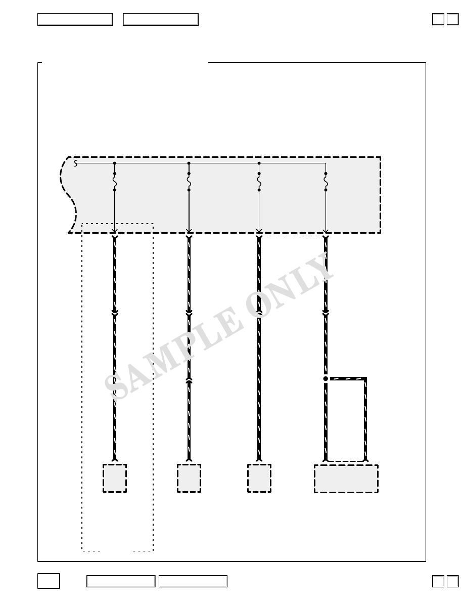
From Fuses to Relays and Components
The second half of Power Distribution shows the wiring “From Fuses to Relays and
Components.” This can speed your troubleshooting by showing which circuits share fuses. If
Power Distribution shows that an inoperative circuit and another circuit share a fuse, check a
component in the other circuit. If it works, you know the fuse is good and power is available to
the inoperative circuit.
STEREO AMPLIFIER
Page 150-3
PHOTO 153
VIEW 106
ALTERNATOR
Page 22
PHOTO 29
POWER
SEAT
CONTROL
UNIT
Page 143-2
PHOTO 124
VIEW 110
DAYTIME
RUNNING
LIGHTS
CONTROL
UNIT
Page 110-12
PHOTO 150
VIEW 65
B
WHT/BLU
5
C405
PHOTO 74
VIEW 60
FUSE 16
(BOSE SYSTEM)
20A
FUSE 15
ACG
7.5A
14
FUSE 10
(RUNNING LIGHT)
10A
WHT/GRN
RED/BLU
6
C405
PHOTO 74
VIEW 60
5
12
WHT/BLU
WHT/BLU
C
2
C414
PHOTO 83
VIEW 91
17
RED/BLU
2
C104
PHOTO 48
VIEW 56
7
WHT/GRN
C442
PHOTO 108
VIEW 92
18
UNDER-
DASH
FUSE/
RELAY
BOX
PHOTO 75
FUSE 11
DR POWER SEAT
20A
RED/WHT
2
C406
PHOTO 74
VIEW 3
5
C413
PHOTO 83
VIEW 73
15
RED/WHT
Canada
RED/WHT
C659
PHOTO 124
VIEW 39
4
WHT/BLU
5
2004 American Honda Motor Co., Inc.
How To Use This Manual
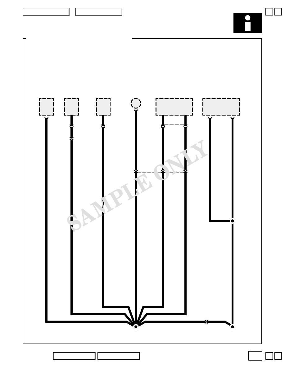
Ground Distribution Schematics
This sample Ground Distribution schematic shows all of the components that share two
ground points.
G601
PHOTO 133
B
9
TCS
CONTROL
UNIT
Page 35
PHOTO 151
VIEW 107
C3
PHOTO 126
2
C613
PHOTO 128
1
6
C793
PHOTO 147
VIEW 6
3
A
4
B
8
FRONT
PASSENGER’S
SEAT HEATER
Page 147
FRONT
PASSENGER’S
SEAT BELT
SWITCH
Page 145
RIGHT
REAR DOOR
ASHTRAY
LIGHT
Page 114
RIGHT REAR
DOOR LATCH
ASSEMBLY
Pages 84-1, 115,
130-1, and 133-6
PHOTO 147
FRONT
PASSENGER’S
POWER SEAT
SWITCH
Page 140
VIEW 102
2
11
C607
PHOTO 131
VIEW 84
14
G631
PHOTO 129
C612
PHOTO 128
1
C611
PHOTO 128
2
Нет комментариевНе стесняйтесь поделиться с нами вашим ценным мнением.
Текст