Acura RL (1996-2004 year). Manual — part 635
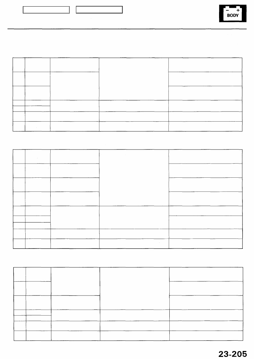
Steering Column Control Unit:
Cavity Wire Test condition
Test: Desired result
Possible cause if result is not obtained
A5
A6
C3
A12
C1
A1
A7
BLK/YEL
WHT/YEL
RED/YEL
BLK
BLK
LT GRN/RED
BLK/WHT
Ignition switch ON (II)
Under all conditions
Under all conditions
Ignition switch ON (II),
and do not operate DPMS
Ignition switch ON (II),
and do not operate DPMS
Check for voltage to ground:
There should be battery voltage.
Check for continuity to ground:
There should be continuity.
Check for voltage to ground:
There should be no voltage.
Check for voltage to ground:
There should be approx. 5 V.
• Blown No. 20 (20 A) fuse in the under-
dash fuse/relay box
• An open in the wire
• Blown No. 56 (7.5 A) fuse in the under-
hood fuse/relay box
• An open in the wire
• Blown No. 54 (20 A) fuse in the under-
hood fuse/relay box
• An open in the wire
• Poor ground (G401, G402 or G251)
• An open in the wire
• An open or short in the wire
• An open or short in the wire
Power Seat Control Unit:
Cavity Wire Test condition
Test: Desired result
Possible cause if result is not obtained
A5
A6
C5
C12
A12
C1
C6
A1
A7
BLK/YEL
WHT/YEL
RED/WHT
WHT/RED
BLK
BLK
BLK
LT GRN/RED
BLK/WHT
Ignition switch ON (II)
Under all conditions
Under all conditions
Under all conditions
Under all conditions
Ignition switch ON (II),
and do not operate DPMS
Ignition switch ON (II),
and do not operate DPMS
Check for voltage to ground:
There should be battery voltage.
Check for continuity to ground:
There should be continuity.
Check for voltage to ground:
There should be no voltage.
Check for voltage to ground:
There should be approx. 5 V.
• Blown No. 20 (20 A) fuse in the under-
dash fuse/relay box
• An open in the wire
• Blown No. 56 (7.5 A) fuse in the under-
hood fuse/relay box
• An open in the wire
• Blown No. 11 (20 A) fuse in the under-
dash fuse/relay box
• An open in the wire
• Blown No. 8 (20 A) fuse in the under-
dash fuse/relay box
• An open in the wire
• Poor ground (G401, G402 or G251)
• An open in the wire
• Poor ground (G651, G681)
• An open in the wire
• An open or short in the wire
• An open or short in the wire
Power Mirror Control Unit:
Cavity Wire Test condition
Test: Desired result
Possible cause if result is not obtained
B1
A6
A11
B9
A12
A1
A7
RED/YEL
(WHT/YEL)
WHT/YEL
YEL/BLK
BLK
BLK
LT GRN/RED
BLK/WHT
Under all conditions
Ignition switch ON (II)
Under all conditions
Ignition switch ON (II),
and do not operate DPMS
Ignition switch ON (II),
and do not operate DPMS
Check for voltage to ground:
There should be battery voltage.
Check for continuity to ground:
There should be continuity.
Check for voltage to ground:
There should be no voltage.
Check for voltage to ground:
There should be approx. 5 V.
• Blown No. 54 (20 A) or No. 56 (7.5 A)
fuse in the under-dash fuse/relay box
• An open in the wire
• Blown No. 56 (7.5 A) fuse in the under-
hood fuse/relay box
• An open in the wire
• Blown No. 19 (7.5 A) fuse in the under-
dash fuse/relay box
• An open in the wire
• Poor ground (G401, G402 or G251)
• An open in the wire
• An open or short in the wire
• An open or short in the wire
Main Menu
Table of Contents
Driving Position Memory System (DPMS)
Troubleshooting
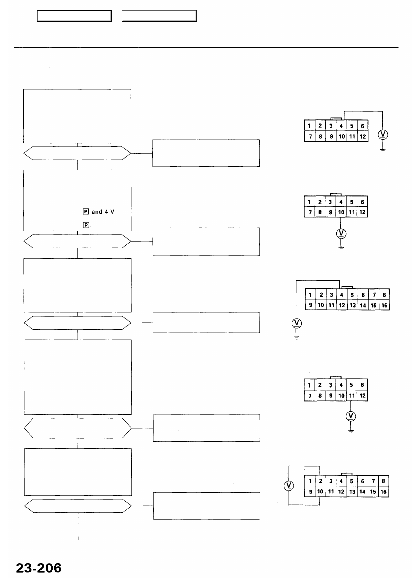
Flowchart No. 1
Ignition Key Switch:
Check for voltage between the col-
umn control unit 12P connector A4
terminal and body ground. There
should be 1 V or less with the igni-
tion key inserted and 4 V or more
with the ignition key removed.
• Open or short in the BLU/WHT
wire
- Faulty ignition key switch
Are voltages as specified?
NO
YES
Transmission Range Switch:
Check for voltage between the col-
umn control unit 12P connector
A10 terminal and body ground.
There should be 1 V or less with
the shift lever in or
more with the shift lever in any
other position than
• Open or short in the BLK/BLU
wire
- Faulty transmission range switch
NO
Are voltages as specified?
YES
Steering Column Auto Switch:
Check for voltage between the
column control unit 16P connec-
tor B4 terminal and body ground.
There should be 1 V or less with
the AUTO switch ON and 4 V or
more with the AUTO switch OFF.
Are voltages as specified?
NO
• Open or short in the LT BLU wire
- Faulty AUTO switch
YES
Vehicle Speed Sensor (VSS):
1. Raise the front of the vehicle,
support it with the safety
stands, put it in neutral, and
slowly rotate one wheel with
other wheel blocked.
2. Check for voltage between the
column control unit 12P con-
nector A11 terminal and body
ground.
Does voltage pulse from O to
about 5 V or more?
• Open or short in the BLU/WHT
wire
- Faulty VSS (see page
NO
YES
Steering Column Position Sensor:
Check for voltage between the
column control unit 16P connec-
tor B2 and B10 terminals.
NOTE: All column control unit
connectors must be connected.
Is there 5 V?
NO • Open or short in the GRY or BRN
wires
• Faulty steering position sensors
YES
COLUMN CONTROL UNIT
16P CONNECTOR "B"
COLUMN CONTROL UNIT
12P CONNECTOR "A"
COLUMN CONTROL UNIT
16P CONNECTOR "B"
NOTE: All connector views are from wire
side of female terminals.
COLUMN CONTROL UNIT
12P CONNECTOR "A"
Main Menu
Table of Contents
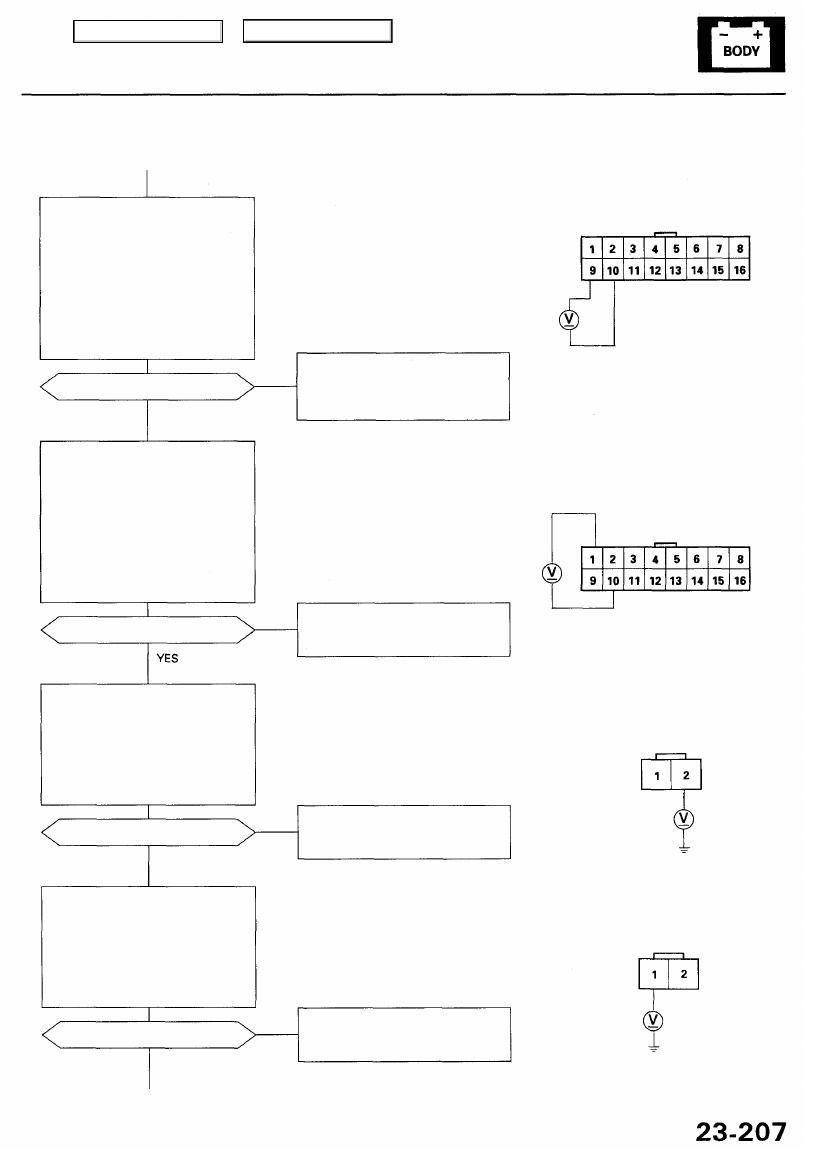
Steering Column Position Sensor
(Extend-retract):
Check for voltage between the col-
umn control unit 16P connector B9
and B10 terminals. There should
be 2.5 V or more with the steering
column in fully-extended position
and 2.5 V or less with the steering
column in fully-retracted position.
NOTE: All column control unit con-
nectors must be connected.
NOTE: If necessary, apply power and
ground to the extend-retract motor to
move the steering column to the fully-
extended and fully-retracted positions
(see page
).
Are voltages as specified?
• Open or short in the PNK or BRN
wires
• Faulty extend-retract position
sensor
NO
YES
NOTE: If necessary, apply power and
ground to the tilt motor to move the
steering column to the fully-up and
fully-down positions (see page
).
Steering Column Position Sensor
(Tilt):
Check for voltage between the col-
umn control unit 16P connector B1
and B10 terminals. There should
be 2.5 V or more with the steering
column in fully-up position and
2.5 V or less with the steering
column in fully-down position.
NOTE: All column control unit con-
nectors must be connected.
Are voltages as specified?
NO
• Open or short in the BLU or BRN
wires
• Faulty tilt position sensor
Extend-retract Motor (Extend):
Check for voltage between the
extend-retract motor 2P connec-
tor No. 2 terminal and body
ground. There should be 12 V
with the extend switch pushed
and no voltage with the extend
switch released.
Are voltages as specified?
• Open or short in the PNK/BLK
wire
• Faulty extend switch
NO
YES
Extend-retract Motor (Retract):
Check for voltage between the
extend-retract motor 2P connec-
tor No. 1 terminal and body
ground. There should be 12 V
with the retract switch pushed
and no voltage with the retract
switch released.
Are voltages as specified?
NO
• Open or short in the GRY/RED
wire
• Faulty retract switch
To page
YES
(cont'd)
NOTE: All connector views are from wire
side of female terminals.
COLUMN CONTROL UNIT
16P CONNECTOR "B"
EXTEND-RETRACT MOTOR
2P CONNECTOR
Main Menu
Table of Contents
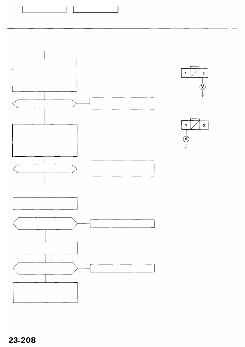
Driving Position Memory System (DPMS)
Troubleshooting (cont'd)
Tilt Motor (Up):
Check for voltage between the tilt
motor 3P connector No. 3 terminal
and body ground. There should be
12V with the tilt-up switch pushed
and no voltage with the tilt-up
switch released.
• Open or short in the BRN wire
• Faulty tilt switch
Are voltages as specified?
NO
YES
Tilt Motor (Down):
Check for voltage between the tilt
motor 3P connector No. 1 terminal
and body ground. There should be
12 V with the tilt-down switch
pushed and no voltage with the
tilt-down switch released.
• Open or short in the LT GRN
wire
• Faulty tilt switch
NO
Are voltages as specified?
YES
Test the extend-retract motor (see
page
).
Does the motor run smoothly
and without noise?
Replace the extend-retract motor.
NO
YES
Test the tilt motor (see page
).
Does the motor run smoothly
and without noise?
NO
Replace the tilt motor.
YES
Substitute a known-good column
control unit, and recheck. If the
systems now work OK, replace
the original column control unit.
TILT MOTOR 3P CONNECTOR
Wire side of
female terminals
Main Menu
Table of Contents
Нет комментариевНе стесняйтесь поделиться с нами вашим ценным мнением.
Текст