Acura RL (1996-2004 year). Manual — part 634
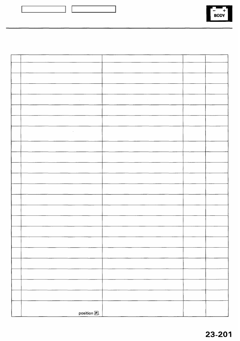
Diagnostic Trouble Code (DTC) Chart
NOTE: Before you proceed with the appropriate flowchart(s), check power and ground as described in the tests on page
DTC
1
2
3
4
5
6
21
22
23
24
25
26
27
28
29
30
31
32
33
34
35
36
37
Symptom
Seat can't be adjusted with the slide
switch.
Seat can't be adjusted with the reclining
switch.
Seat front height can't be adjusted with
the front up-down switch.
Seat rear height can't be adjusted with the
rear up-down switch.
Steering column can't be adjusted with
the tilt switch.
Steering column can't be adjusted with
the extend-retract switch.
Positions can't be stored with the ignition
switch ON (II) and the MEMO button
pressed.
Positions can't be stored or retrieved with
position button 1.
Positions can't be stored or retrieved with
position button 2.
Seat can't be adjusted forward with the
slide switch.
Seat can't be adjusted backward with the
slide switch.
Seat can't be adjusted forward with the
recline switch.
Seat can't be adjusted backward with the
recline switch.
Seat front height can't be adjusted with
the front up switch.
Seat front height can't be adjusted with
the front down switch.
Seat rear height can't be adjusted with the
rear up switch.
Seat rear height can't be adjusted with the
rear down switch.
Steering column can't be adjusted with
the tilt-up switch.
Steering column can't be adjusted with
the tilt-down switch.
Steering column can't be adjusted with
the extend switch.
Steering column can't be adjusted with
the retract switch.
Steering column doesn't tilt up and retract
when the ignition key is pulled out.
Steering column doesn't tilt up, or the
steering column position cannot be
retrieved with the shift lever in
Possible Cause
Fault in slide switch or slide switch wiring
Fault in recline switch or recline switch
wiring
Fault in front up-down switch or front
up-down switch wiring
Fault in rear up-down switch or rear
up-down switch wiring
Fault in tilt switch or tilt switch wiring
Fault in extend-retract switch or
extend-retract switch wiring
Fault in MEMO button wiring or common
wiring of switches
Fault in position button 1 wiring or
common wiring of switches
Fault in position button 2 wiring or
common wiring of switches
Fault in forward slide switch wiring or
common wiring of switches
Fault in backward slide switch wiring or
common wiring of switches
Fault in forward recline switch wiring or
common wiring of switches
Fault in backward recline switch wiring or
common wiring of switches
Fault in front up switch wiring or common
wiring of switches
Fault in front down switch wiring or
common wiring of switches
Fault in rear up switch wiring or common
wiring of switches
Fault in rear down switch wiring or
common wiring of switches
Fault in tilt-up switch wiring or common
wiring of switches
Fault in tilt-down switch wiring or
common wiring of switches
Fault in extend switch wiring or common
wiring of switches
Fault in retract switch wiring or common
wiring of switches
Fault in the ignition switch or ignition
switch wiring
Fault in the transmission range switch or
transmission range switch
Flowchart
3
4
5
6
7
8
9
9
9
3
3
4
4
5
5
6
6
7
7
8
8
1
1
Page
Main Menu
Table of Contents
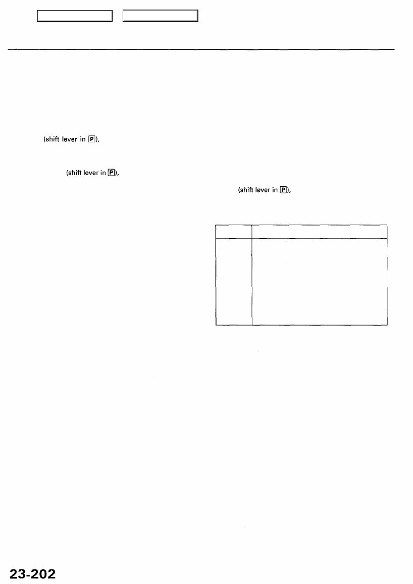
Driving Position Memory System (DPMS)
Troubleshooting Guide
After completing the pre-troubleshooting tests (see page
), select the flowchart(s) listed on the next page for the
symptom(s) you want to troubleshoot. If the symptom(s) are related to automatic adjusting, first read the explanation for
the automatic adjustment modes.
Automatic Adjustment Modes
Mode 1: When the ignition key is pulled out (ignition switch turned OFF) with the AUTO switch ON and the vehicle parked
the steering column automatically moves to the highest tilt position and the fully-retracted
position to ease exit from the vehicle.
Mode 2: When the ignition key is inserted at the end of mode 1, without turning the ignition switch ON (II) and the vehicle
parked the steering column will return to the position it was in before mode 1 began.
Mode 3: When one of position buttons is pressed with the vehicle parked and the ignition key is inserted,
the steering column, the seat and the mirrors will move to their memorized positions.
NOTE: The priority of the automatic adjustments are shown:
• If the ignition key is not inserted, the steering column
is not adjusted at No. 3 to No. 4. It will be adjusted at
No. 9 to No. 10 only after the key is inserted.
• If the ignition key is inserted while No. 1 and No. 2
are carried out, the steering column will be adjusted
at No. 3 and No. 4.
Priority
1
2
3
4
5
6
7
8
9
10
Devices
Seat slide (backward), mirror
Seat recline (backward)
Tilt
Extend-retract
Seat slide (forward)
Seat recline (forward)
Seat front up-down
Seat rear up-down
Tilt
Extend-retract
Main Menu
Table of Contents
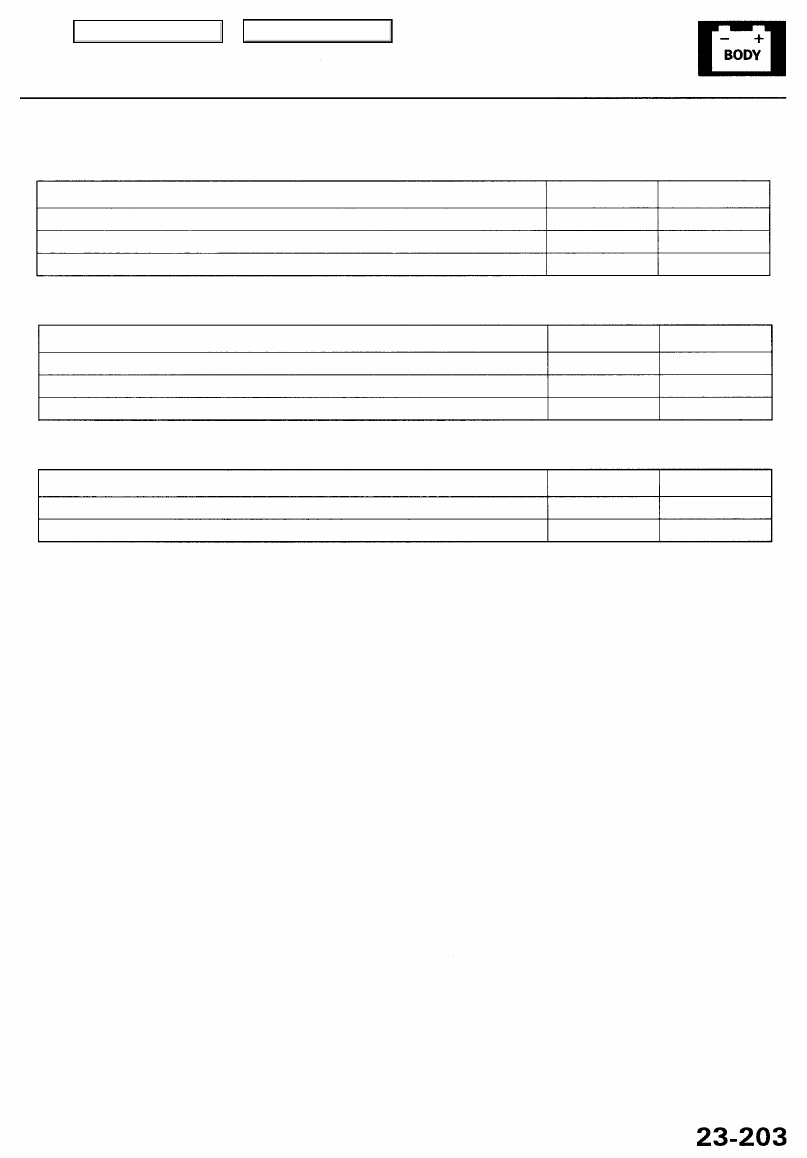
Automatic Adjustments
Symptom
Adjustment mode 1 doesn't work.
Adjustment mode 2 doesn't work.
Adjustment mode 3 doesn't work.
Flowchart
1
1
2
Page
Manual Adjustments
Symptom
The steering column doesn't work.
The driver's power seat doesn't work.
The power mirror doesn't work with the ignition switch ON (II).
Flowchart(s)
7,8
3, 4, 5, 6
10
Page(s)
to
Others
Symptom
The driving position cannot be stored.
The position button indicators do not come on or do not blink.
Flowchart
9
11
Page
Communication Lines:
NOTE: There are two communication lines between the steering column control unit and the power seat control unit, and
two communication lines between the steering column control unit and the power mirror control unit. If one communica-
tion line is faulty, the systems still functions via the other line. If the automatic adjustments stop working, but each compo-
nent can still be adjusted manually, then both communication lines are faulty.
Main Menu
Table of Contents
Driving Position Memory System (DPMS)
12P CONNECTOR "A"
16P CONNECTOR "B"
8P CONNECTOR "C"
Power Seat Control Unit:
12P CONNECTOR "A"
16P CONNECTOR "B"
12P CONNECTOR "C"
Power Mirror Control Unit:
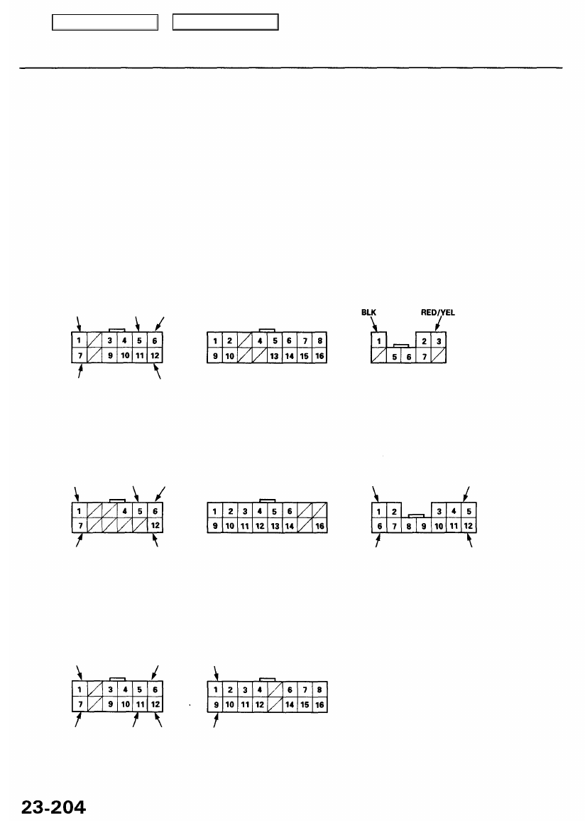
Pre-troubleshooting Tests
Before troubleshooting the DTC(s) indicated by the LEDs in the position buttons of the memory switch, or before selecting
a flowchart from the troubleshooting guide on page
, make the following tests to check power and ground.
NOTE:
• Be careful not to cause shorts or damage wire insulation when back-probing.
• In the tests, "column control unit" stands for "steering column control unit", mirror control unit" stands for "power
mirror control unit", seat control unit" stands for "power seat control unit".
• All connector views are from wire side of female terminals.
Inspect the connector and socket terminals to be sure they are all making good contact.
• If the terminals are bent, loose or corroded, repair them as necessary, and recheck the system.
• If the terminals look OK, make voltage and continuity checks at the connectors.
Steering Column Control Unit:
12P CONNECTOR "A"
16P CONNECTOR "B"
RED/YEL ('96 - 98 models) or WHT/YEL ('99 model)
LT GRN/RED WHT/YEL
BLK/WHT YEL/BLK BLK
BLK
LT GRN/RED BLK/YEL WHT/YEL
BLK/WHT BLK
BLK/WHT BLK
LT GRN/RED BLK/YEL WHT/YEL
BLK WHT/RED
BLK RED/WHT
Main Menu
Table of Contents
Нет комментариевНе стесняйтесь поделиться с нами вашим ценным мнением.
Текст