Acura RL (1996-2004 year). Manual — part 479
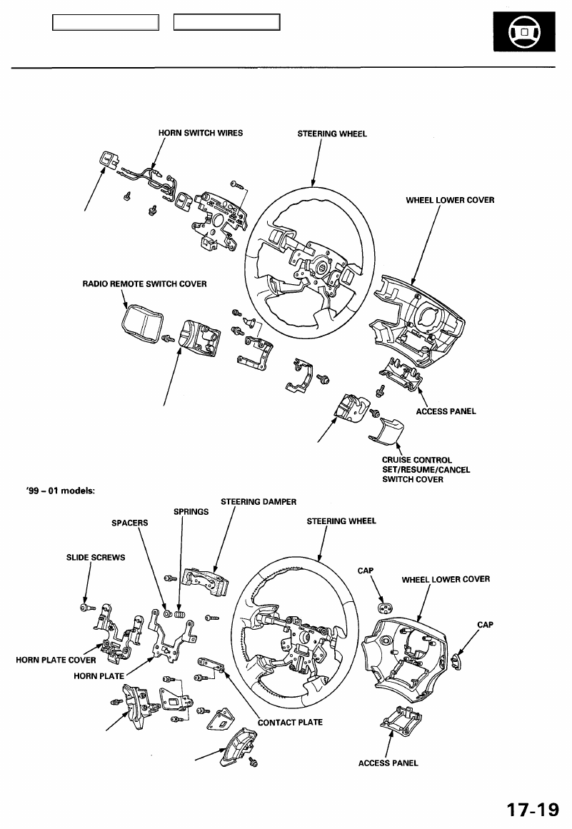
Disassembly/Reassembly
'96 - 98 models:
CRUISE CONTROL
SET/RESUME/CANCEL
SWITCH
Test, see
RADIO REMOTE SWITCH
RADIO REMOTE SWITCH
CRUISE CONTROL
SET/RESUME/CANCEL
Main Menu
Table of Contents
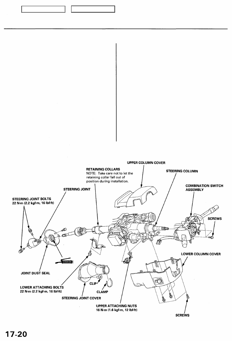
Steering Column
Removal/Installation
SRS components are located in this area. Review the
SRS component locations, precautions, and procedures
in the SRS (
) before performing repairs or ser-
vice.
NOTE: Before removing the steering column, remove
the driver's airbag assembly and cable reel (see
).
CAUTION:
• On vehicles with VSA ('00 - 01 models only), do not
remove the steering angle sensor from the combina-
tion switch.
• When removing and installing the combination
switch, keep grease, oil, dirt, and foreign objects out
of the steering angle sensor.
1. Remove the steering wheel (see page
).
2. Remove the driver's side dashboard lower cover and
).
3. Remove the column covers.
4. Remove the combination switch assembly from the
steering column shaft by disconnecting the connec-
tors and removing the screws.
5. Disconnect the ignition switch connectors, the
tilt/extend-retract motor connectors and the sensor
connectors.
6. Remove the steering joint cover.
7. Disconnect the steering joint, and remove it from the
column shaft.
8. Remove the steering column by removing the attach-
ing nuts and bolt.
9. Installation is the reverse of the removal procedure.
CAUTION: Alternately tighten the upper attaching
nuts and lower attaching bolts in several steps.
Tighten the upper attaching nuts to the specified
torque to last.
Main Menu
Table of Contents
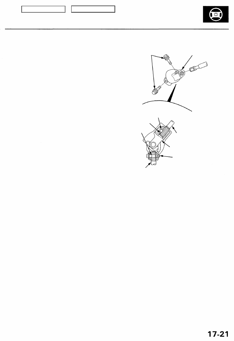
NOTE:
• Make sure the steering joint is connected as follows:
a. Insert the upper end of the steering joint onto the
steering shaft (line up the bolt hole with the flat on
the shaft), and loosely install the upper joint bolt,
b. Slip the lower end of the steering joint onto the
pinion shaft (line up the bolt hole with the groove
around the shaft), and loosely install the lower
joint bolt. Be sure that the lower joint bolt is
securely in the groove in the pinion shaft,
c. Pull on the steering joint to make sure that the steer-
ing joint is fully seated. Then tighten the joint bolts.
• Be sure the wires are not caught or pinched by any
parts when installing the column.
• Make sure the wire harness is routed and fastened
properly.
• Make sure the connectors are properly connected.
• '00 - 01 Models: After installing the steering column,
perform the steering angle sensor neutral position
memorizing (see page
).
STEERING JOINT BOLTS
22 N-m (2.2 kgf-m, 16 Ibf-ft)
STEERING JOINT
UPPER JOINT BOLT
Bolt must line up
with flat on shaft.
Flat portion.
Groove.
STEERING
SHAFT
STEERING JOINT
LOWER JOINT BOLT
Bolt must line up with
groove around on shaft.
PINION
SHAFT
Main Menu
Table of Contents
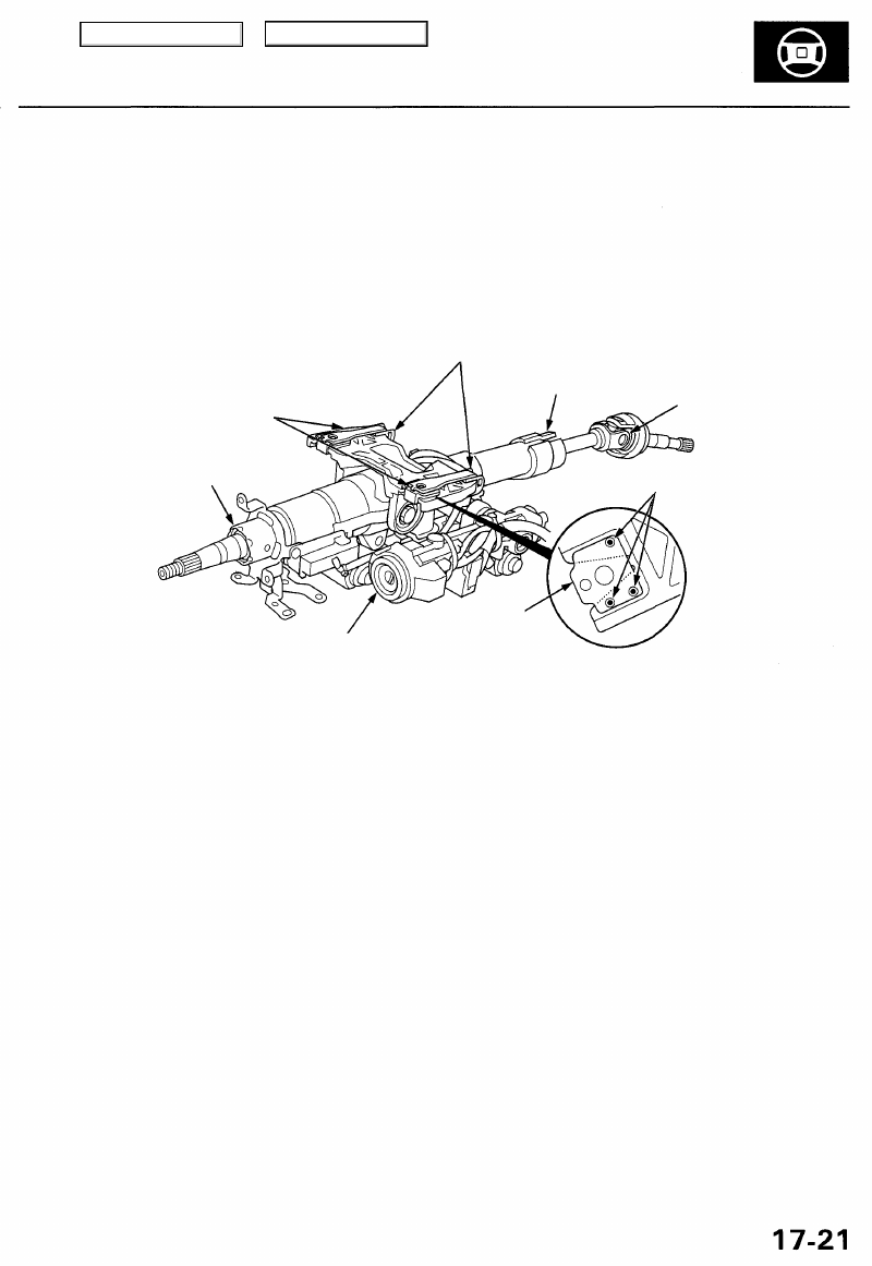
Inspection
• For tilt/extend-retract motors and sensors inspection,
refer to the Driving Position Memory System (DPMS)
in the
• Check the steering column bail bearing and the steering
joint bearings for play and proper movement. If there is
noisy or if there is excessive play, replace the steering
column as an assembly.
• Check the retaining collars for damage. If they are dam-
aged, replace the retaining collars.
• Check the absorbing plates, absorbing plate guides
and sliding capsules for distortion and breakage.
Replace the steering column as an assembly if they
are distorted or broken.
ABSORBING PLATES
COLUMN BALL BEARING
ABSORBING PLATE GUIDES
STEERING JOINT
BEARINGS
PLASTIC
INJECTIONS
SLIDING CAPSULE
This part is attached
to the column bracket
with the plastic injections.
RETAINING COLLARS
Main Menu
Table of Contents
Нет комментариевНе стесняйтесь поделиться с нами вашим ценным мнением.
Текст