Acura RL (1996-2004 year). Manual — part 522
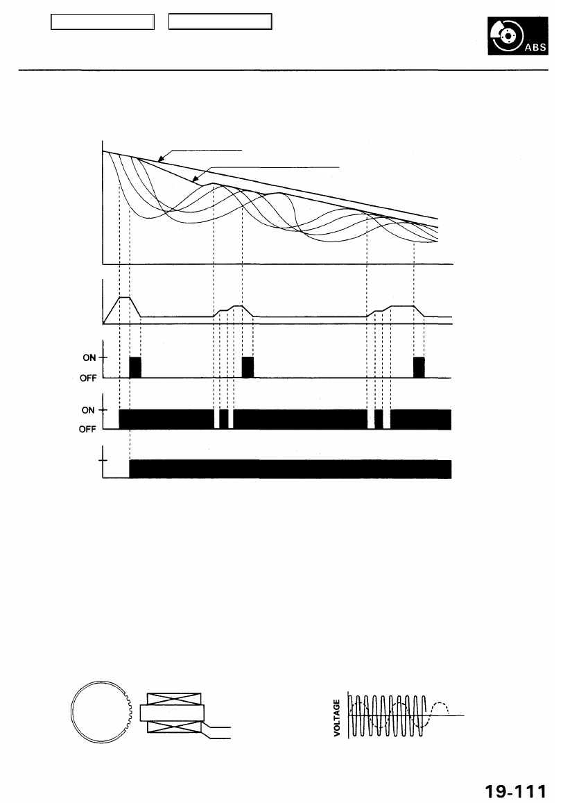
Wheel Speed and Modulator Control
SPEED
VEHICLE
SPEED
REFERENCE
VEHICLE
SPEED
PRESSURE
OUTLET
VALVE
INLET
VALVE
MOTOR
ON
OFF
WHEEL SPEED
TIME
When the wheel speed drops sharply below the vehicle speed, the inlet valve closes to retain the caliper fluid pressure.
When the wheel speed drops further, the outlet valve opens momentarily to reduce the caliper fluid pressure. The pump
motor starts at this time.
As the wheel speed is restored, the inlet valve opens momentarily to increase the caliper fluid pressure.
Wheel Sensor
The wheel sensors are the magnetic contactless type. As the gear pulser teeth rotate past the wheel sensor's magnetic
coil, AC current is generated. The AC frequency changes in accordance with the wheel speed. The ABS control unit detects
the wheel sensor signal frequency and thereby detects the wheel speed.
GEAR PULSER
WHEEL SENSOR
at HIGH SPEED
at LOW SPEED
Main Menu
Table of Contents
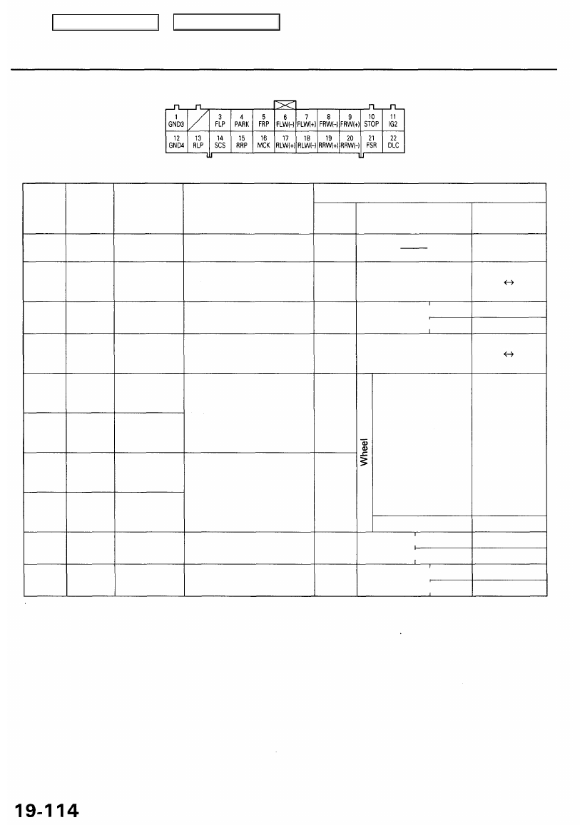
ABS Control Unit Terminal Arrangement
ABS CONTROL UNIT 22P CONNECTOR
Wire side of female terminals
Terminal
number
1
3
4
5
6
7
8
9
10
11
Wire
color
BLK
WHT/RED*
GRN/RED
WHT/GRN*
BRN
GRN/BLU
GRN
GRN/BLK
GRN/WHT
YEL/BLK
Terminal sign
(Terminal
name)
GND3
(Ground 3)
FLP
(Front-left
pulse)
PARK
(Parking)
FRP
(Front-right
pulse)
FLW (-)
(Front-left
wheel negative)
FLW (+)
(Front-left
wheel positive)
FRW (-)
(Front-right
wheel negative)
FRW (+)
(Front-right
wheel positive)
STOP
IG2
(Ignition 2)
Description
Ground
Outputs left-front wheel
sensor signal
Detects parking brake
switch signal
Outputs right-front wheel
sensor signal
Detects left-front wheel
sensor signal
Detects right-front wheel
sensor signal
Detects brake pedal posi-
tion switch signal
Power source for activating
the system
Measurement
Terminal
1-GND
3-GND
4-GND
5-GND
10-GND
11-GND
Conditions
(Ignition switch ON (ID)
Spin wheel slowly
Parking brake Pressed
pedal Released
Spin wheel slowly
Spin wheel at
1 turn/second
Stopped
Brake Pressed
pedal Released
Ignition ON (II)
switch Start (III)
Voltage
Below 0.3 V
5 V 0 V
Below 0.3 V
Battery Voltage
5 V 0 V
AC:
0.053 V or
above
(Reference)
Oscilloscope:
0.15Vp-p or
above
0.25-1. 15V
Battery Voltage
Below 0.3 V
Battery Voltage
Below 0.3 V
*: With TCS only
Main Menu
Table of Contents
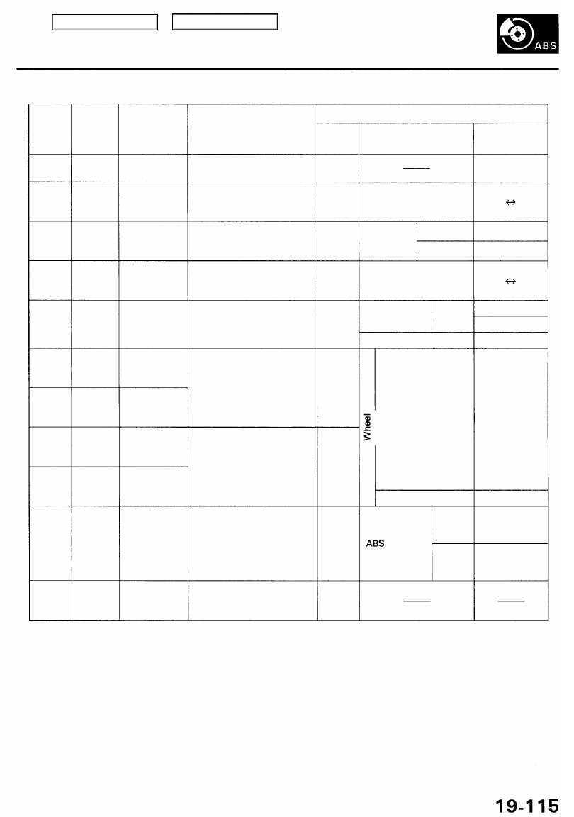
Terminal
number
12
13
14
15
16
17
18
19
20
21
22
Wire
color
BLK
GRY/WHT*
RED
GRY/BLK*
GRN
LT BLU
GRY
GRN/YEL
BLU/YEL
YEL/GRN
RED
Terminal sign
(Terminal name)
GND4
(Ground 4)
RLP
(Rear-left
pulse)
SCS
(Service check
signal)
RRP
(Rear-right
pulse)
MCK
(Motor check)
RLW (+)
(Rear-left
wheel positive)
RLW (-)
(Rear-left
wheel negative)
RRW (+)
(Rear-right
wheel positive)
RRW (-)
(Rear-right
wheel negative)
FSR
(Fail-safe
relay)
DLC
(Data link
connector)
Description
Ground
Outputs left-rear wheel
sensor signal
Detects service check con-
nector signal (DTC indica-
tion or DTC erasure)
Outputs right-rear wheel
sensor signal
Detects pump motor drive
signal
Detects left-rear wheel
sensor signal
Detects right-rear wheel
sensor signal
Drives fail-safe relay
(Fail-safe relay is turned
OFF to shut off the power
source to the solenoid and
pump motor relay when
problem occurs.)
Communicates with the
Honda PGM Tester
Measurement
Terminal
12-GND
13-GND
14-GND
15-GND
16-GND
21-GND
22-GND
Conditions
(Ignition switch ON (ID)
Spin wheel slowly
SCS service Connected
connector
Disconnected
Turn wheel slowly
ON
Pump motor —————
OFF
Remove MCK fuse
Turn wheel at
1 turn/second
Stopped
Warning
Normal
Voltage
Below 0.3 V
5 V 0 V
Below 0.3 V
About 5 V
5 V 0 V
Battery Voltage
Below 0.3 V
About 10 V
AC:
0.053 V or
above
(Reference)
Oscilloscope:
0.15 Vp-p or
above
0.25 -1.15V
Below 0.3 V
About 1 1 V
*: With TCS only
Main Menu
Table of Contents
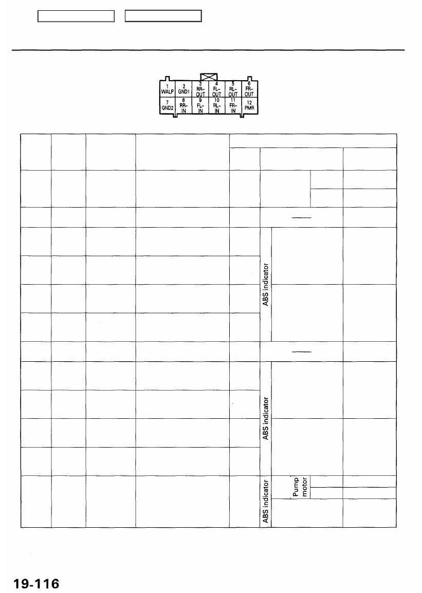
ABS Control Unit Terminal Arrangement
ABS CONTROL UNIT 12P CONNECTOR
Wire side of female terminals
Terminal
number
1
2
3
4
5
6
7
8
9
10
11
12
Wire
color
BLU/WHT
BLK
BLK/ORN
YEL/BLU
YEL/WHT
YEL/BLK
BLK
YEL
RED/BLU
RED/WHT
RED/BLK
YEL/RED
Terminal sign
(Terminal name)
WALP
(Warning lamp)
GND1
(Ground 1)
RR-OUT
(Rear-right
outlet)
FL-OUT
(Front-left
outlet)
RL-OUT
(Rear-left
outlet)
FR-OUT
(Front-right
outlet)
GND2
(Ground 2)
RR-IN
(Rear-right
inlet)
FL-IN
(Front-left
inlet)
RL-IN
(Rear-left
inlet)
FR-IN
(Front-right
inlet)
PMR
(Pump motor
relay)
Description
Drives ABS indicator
(Turns the indicator drive
transistor to ON, then turns
off the indicator)
Ground
Drives right-rear outlet
solenoid valve
Drives left-front outlet
solenoid valve
Drives left-rear outlet
solenoid valve
Drives right-front outlet
solenoid valve
Ground
Drives right-rear inlet
solenoid valve
Drives left-front inlet
solenoid valve
Drives left-rear inlet
solenoid valve
Drives right-front inlet
solenoid valve
Drives pump motor relay
Measurement
Terminal
1-GND
2-GND
3-GND
4-GND
5-GND
6-GND
7-GND
8-GND
9-GND
10-GND
11-GND
12-GND
Conditions
(Ignition switch ON (ID)
ABS indicator
ON
OFF
OFF
ON
OFF
ON
OFF
ON
OFF
ON
Voltage
4 - 6 V
Below 0.3 V
Below 0.3 V
Battery Voltage
Below 0.3 V
Below 0.3 V
Battery Voltage
Below 0.3 V
Below 1.0V
Battery Voltage
Below 0.3 V
Main Menu
Table of Contents
Нет комментариевНе стесняйтесь поделиться с нами вашим ценным мнением.
Текст