Acura RL (1996-2004 year). Manual — part 511
Troubleshooting
DTC 4-1 (Right-front), 4-2 (Left-front), 4-4 (Right-rear), 4-8 (Left-rear):
Wheel Sensor (cont'd)
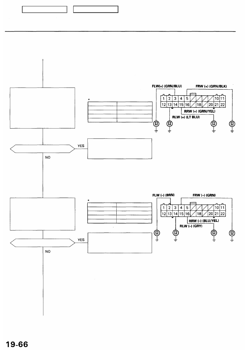
ABS CONTROL UNIT 22P CONNECTOR
Check for a short to body ground
in the wheel sensor positive (+)
circuit:
1. Disconnect the ABS control
unit 22P connector.
2. Check for continuity between
the appropriate wheel sensor
positive (+) circuit terminal*
and body ground.
NOTE: Check with the appropriate wheel
sensor 2P connector disconnected.
DTC
4-1 (Right-front)
4-2 (Left-front)
4-4 (Right-rear)
4-8 (Left-rear)
Appropriate Terminal
No. 5: FRW (+)
No. 3: FLW (+)
No. 15: RRW(+)
No. 13: RLW (+)
Is there continuity?
Repair short to body ground in the
positive (+) circuit wire between
the ABS control unit and appropri-
ate wheel sensor.
Wire side of female terminals
Check for a short to body ground
in the wheel sensor negative (-)
circuit:
Check for continuity between the
appropriate wheel sensor nega-
tive (-) circuit terminal* and body
ground.
DTC
4-1 (Right-front)
4-2 (Left-front)
4-4 (Right-rear)
4-8 (Left-rear)
Appropriate Terminal
No. 4: FRW (-)
No. 2: FLW (-)
No. 16: RRW (-)
No. 14: RLW (-)
Is there continuity?
Repair short to body ground in the
negative (-) circuit wire between
the ABS control unit and appropri-
ate wheel sensor.
Main Menu
Table of Contents
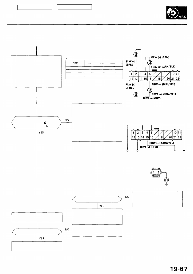
) ABS CONTROL UNIT 22P CONNECTOR
FLW (+) (GRN/BLU)
Check the wheel sensor resis-
tance:
1. Connect the wheel sensor 2P
connector.
2. Measure the resistance
between the ABS control unit
22P connector positive side
and negative side terminals of
the appropriate wheel sensor*.
Is the resistance as specified?
— Front: 700- 1,100
— Rear: 1,400-2,000
Check for an open in the wheel
sensor circuit:
1. Connect the ABS control unit
22P connector appropriate
positive side terminal* to body
ground with a jumper wire.
2. Disconnect the appropriate
wheel sensor* 2P connector.
3. Check for continuity between
terminal No. 2 and body
ground.
Wire side of female terminals
NOTE: Check with the ABS control unit 22P
connector disconnected.
FLW (+) (GRN/BLU)
FRW (+) (GRN/BLK)
WHEEL SENSOR 2P CONNECTOR
Terminal side of
male terminals
Is there continuity?
Repair open in the positive (+) cir-
cuit wire between the ABS con-
trol unit and appropriate wheel
sensor.
Repair open in the negative (-) cir-
cuit wire between the ABS con-
trol unit and appropriate wheel
sensor.
Correct the appropriate wheel
sensor air gap.
Measure the appropriate wheel
sensor air gap (see page 19-103).
Is the air gap OK?
Check the ABS function (see page
).
JUMPER WIRE
JUMPER WIRE
Appropriate Terminal
Positive Side Negative Side
4-1 (Right-front) No. 5: FRW (+) No. 4: FRW (-)
4-2 (Left-front) No. 3: FLW (+) No. 2: FLW (-)
4-4 (Right-rear) No. 15: RRW (+) No. 16: RRW (-)
4-8 (Left-rear) No.13: RLW (+) No. 14: RLW (-)
Main Menu
Table of Contents
Troubleshooting
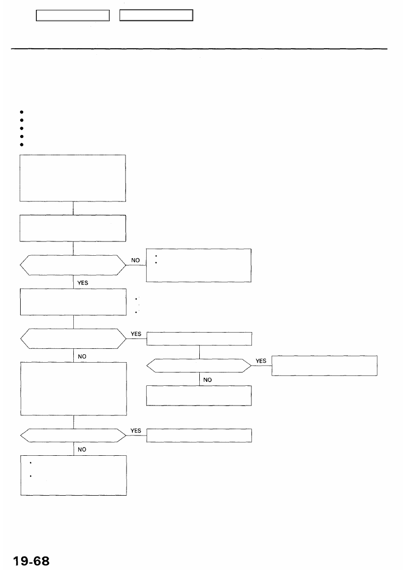
DTC 5, 5-4, 5-8: Rear Wheel Lock
The ABS control unit monitors the rear wheel sensor signals during the regular diagnosis (during driving). This diagnosis
is not performed when the parking brake signal is ON. The ABS control unit turns the ABS indicator light on if it detects no
signal(s) from the rear wheel sensor(s) due to, for example, rear wheel lock.
Possible causes:
Wheel spin during cornering
Open circuit, internal short or short to the body ground in the wheel sensor system
Rear brake drag
Modulator does not decrease pressure properly
Faulty ABS control unit
— When vehicle is driven, ABS
indicator light is ON.
— With the SCS service connec-
),
DTCs 5, 5-4 and/or 5-8 are indi-
cated.
Check the PARK circuit:
1. Turn the ignition switch ON (II).
2. Press the parking brake pedal.
Does the brake system light
come on?
Parking brake switch stuck OFF.
Repair open circuit between the
under-dash fuse/relay box and
parking brake switch.
NOTE:
The self-diagnosis of the wheel sensor is per-
formed in this step.
Test-drive with the parking brake released.
Does the ABS indicator light
come on?
Check for rear brake drag:
1. Raise the rear of the vehicle,
and support it with safety
stands (see
).
2. Spin the left and/or right rear
wheel and check for brake
drag.
Is code 4-4 or 4-8 indicated?
Perform the troubleshooting for
the rear wheel sensor.
Perform the appropriate trouble-
shooting for the code.
Does the brake drag?
Repair the rear brake drag.
Check the ABS function (see
page
).
The probable cause was that
traction was lost due to exces-
sive cornering speed, etc.
Check the self-diagnosis:
Test-drive the vehicle at speeds
of 6 mph (10 km/h) or more.
).
Main Menu
Table of Contents
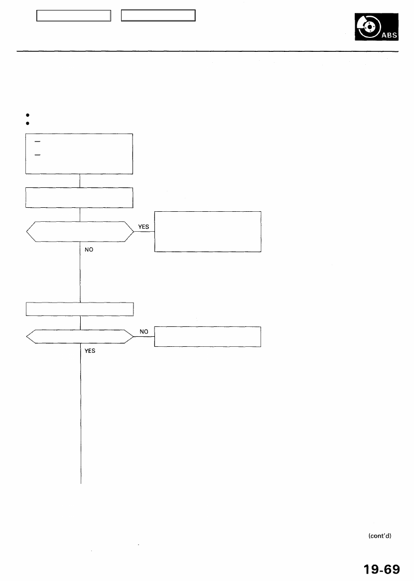
DTC 6: Front and Rear Fail-safe Relays
The ABS control unit monitors the voltage from the battery for the six solenoids during the initial diagnosis when the fail-
safe relays are OFF. The ABS control unit keeps the ABS indicator light on if it detects battery voltage at the front and rear
solenoid circuits.
Possible causes:
Short to power in the relay drive circuits between the fail-safe relays and ABS control unit
Faulty relay drive transistor (ON) in the ABS control unit
Does the ABS indicator light go
off?
The ABS is OK at this time. Check
for damaged wire harness
between the ABS control unit,
solenoids and fail-safe relays (inter-
mittent short to power).
Is code 6 indicated?
Perform the appropriate trouble-
shooting for the code.
With engine running, ABS indi-
cator light is ON.
With the SCS service connec-
tor connected (see page
),
DTC 6 is indicated.
Problem verification:
Start the engine.
Confirm the DTC that appears first.
Main Menu
Table of Contents
Нет комментариевНе стесняйтесь поделиться с нами вашим ценным мнением.
Текст