Acura RL (1996-2004 year). Manual — part 498

Master Cylinder/Brake Booster
Removal/Installation
CAUTION:
Be careful not to bend or damage the brake lines
when removing the master cylinder.
Do not spill brake fluid on the vehicle; it may damage
the paint; if brake fluid does contact the paint, wash
it off immediately with water.
To prevent spills, cover the hose joints with rags or
shop towels.
1. Disconnect the brake fluid level switch connectors.
2. Remove the reservoir cap from the master cylinder.
3. Remove the brake fluid from the master cylinder
reservoir with a syringe.
4. Disconnect the brake lines from the master cylinder.
5. Remove the master cylinder mounting nuts.
6. Remove the master cylinder from the brake booster.
7. Disconnect the vacuum hose from the brake booster.
8. Remove the cotter pin and clevis pin from the clevis.
CAUTION: Do not disconnect the clevis by remov-
ing it from the operating rod of the brake booster. If
the clevis is loosened, adjust the pushrod length
before installing the brake booster (see page
).
NOTE: '96 - 97 models shown.
9. Remove the four brake booster mounting nuts.
10. Pull the brake booster forward until the clevis is
clear of the bulkhead.
11. Remove the brake booster from the engine com-
partment.
12. Install the brake booster and master cylinder in the
reverse order of removal.
CAUTION:
When connecting the brake lines, make sure
there is no interference between the brake lines
and other parts.
Be careful not to bend or damage the brake lines
when installing the master cylinder.
NOTE: If replacing the master cylinder or brake
booster, check and adjust the pushrod clearance
before installing the master cylinder (see page
).
13. Fill the master cylinder reservoir, and bleed the
).
14. After installation, check the brake pedal height and
brake pedal free play (see page
), and adjust if
necessary.
VACUUM HOSE
COTTER PIN
Replace.
12 N-m (1.3 kgf-m, 9 Ibf-ft)
BRAKE BOOSTER
Do not disassemble.
BRAKE FLUID LEVEL
SWITCH CONNECTORS
MASTER
CYLINDER
Do not disassemble.
13 N-m (1.3 kgf-m, 9 Ibf-ft)
To ABS modulator unit
14 N-m 11.5 kgf-m, 11 Ibf-ft)
CLEVIS
JOINT PIN
Main Menu
Table of Contents
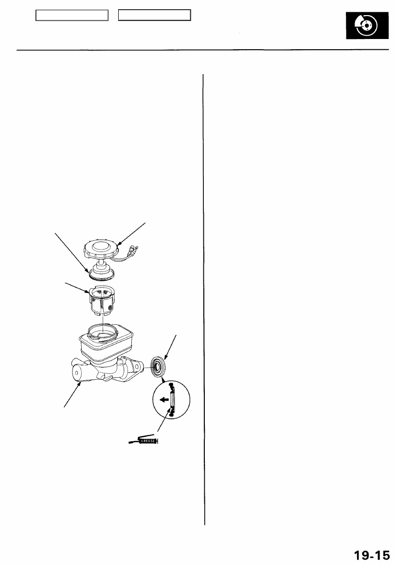
Master Cylinder Inspection
CAUTION:
• Do not spill brake fluid on the vehicle; it may damage
the paint; if brake fluid does contact the paint, wash
it off immediately with water.
• Before reassembling, check that all parts are free of
dust and other foreign particles.
• Do not try to disassemble the master cylinder assem-
bly. Replace the master cylinder assembly with a
new one if necessary.
• Make sure no dirt or other foreign matter is allowed
to contaminate the brake fluid.
NOTE: '96 - 97 models shown.
RESERVOIR SEAL
Check for damage and
deterioration.
RESERVOIR CAP
Check for blockage
and vent holes.
STRAINER
Remove accumulated
sediment.
ROD SEAL
Check for damage
and deterioration.
MASTER CYLINDER
Check for leaks, rust, and damage.
SILICONE GREASE
Main Menu
Table of Contents
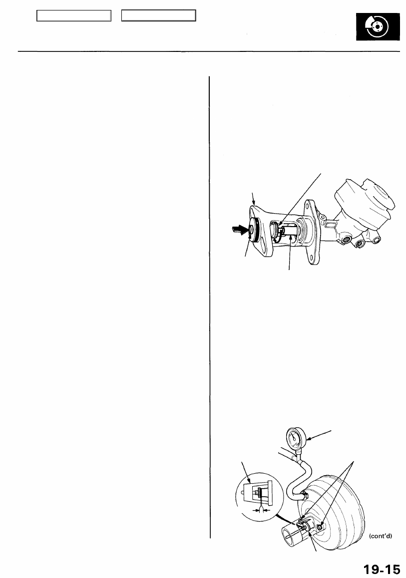
CENTER
SHAFT
SECONDARY PISTON
PUSHROD
ADJUSTMENT GAUGE
07JAG-SD40100
CLEARANCE
ADJUSTING NUT
Pushrod Clearance Adjustment
NOTE: Master cylinder pushrod-to-piston clearance must
be checked and adjustments made, if necessary, before
installing the master cylinder.
1. Set the special tool on the master cylinder body;
push in the center shaft until the top of it contacts the
end of the secondary piston by turning the adjusting
nut.
NOTE: '96 - 97 models shown.
PUSHROD
ADJUSTMENT
GAUGE
ADJUSTING NUT
2. Without disturbing the center shaft's position, install
the special tool upside down on the booster.
3. Install the master cylinder nuts, and tighten them to
the specified torque.
4. Connect the booster in-line with a vacuum gauge 0 -
101 kPa (0 - 760 mmHg, 30 in Hg) to the booster's
engine vacuum supply, and maintain an engine
speed that will deliver 66 kPa (500 mmHg, 20 in Hg)
vacuum.
5. With a feeler gauge, measure the clearance between
the gauge body and the adjusting nut as shown.
Clearance: 0 - 0.2 mm (0 - 0.008 in)
VACUUM GAUGE
(Commercially available)
0 - 101 kPa
(0 - 760 mm.Hg, 30 in.Hg)
MASTER CYLINDER NUT
15 N-m (1.5 kgf-m, 11 Ibf-ft)
Main Menu
Table of Contents
Master Cylinder/Brake Booster
Pushrod Clearance Adjustment
(cont'd)
NOTE: If the clearance between the gauge body and
adjusting nut is 0.2 mm (0.008 in), the pushrod-to-piston
clearance is 0 mm. However, if the clearance between
the gauge body and adjusting nut is 0 mm, the pushrod-
to-piston clearance is 0.2 mm (0.008 in) or more.
Therefore it must be adjusted and rechecked.
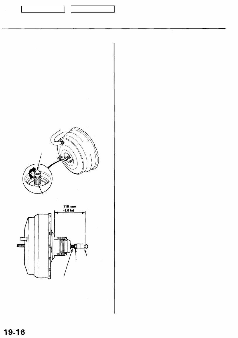
6. If the clearance is incorrect, remove the tool, and
adjust the clearance by holding the pushrod and
turning the adjuster in or out.
CAUTION: Do not pull the pushrod out of the brake
booster.
NOTE: Adjust the clearance while the specified vac-
uum is applied to the booster.
ADJUSTER
PUSHROD
7. Adjust the pushrod length as shown if the booster
is removed.
8. Install the master cylinder (see page
).
PUSHROD
LOCKNUT
15 N-m
(1.5 kgf-m,
11 Ibf-ft)
CLEVIS
Main Menu
Table of Contents
Нет комментариевНе стесняйтесь поделиться с нами вашим ценным мнением.
Текст