Acura RL (1996-2004 year). Manual — part 499

Master Cylinder/Brake Booster
Brake Booster Inspection
Functional Test
1. With the engine stopped, press the brake pedal sev-
eral times to deplete the vacuum reservoir, then
press the pedal hard and hold it for 15 seconds. If
the pedal sinks, either the master cylinder is
bypassing internally, or the brake system (master
cylinder, lines, modulator, or caliper) is leaking.
2. Start the engine with the pedal pressed. If the pedal
sinks slightly, the vacuum booster is operating nor-
mally. If the pedal height does not vary, the booster
or check valve is faulty.
3. With the engine running, press the brake pedal light-
ly. Apply just enough pressure to hold back auto-
matic transmission creep. If the brake pedal sinks
more than 25 mm (1.0 in.) in 3 minutes, the master
cylinder is faulty. A slight change in pedal height
when the A/C compressor cycles on and off is nor-
mal. (The A/C compressor load changes the vacuum
available to the booster.)
Leak Test
1. Press the brake pedal with the engine running, then
stop the engine. If the pedal height does not vary
while pressed for 30 seconds, the vacuum booster is
OK. If the pedal rises, the booster is faulty.
2. With the engine stopped, press the brake pedal sev-
eral times using normal pressure. When the pedal is
first pressed, it should be low. On consecutive appli-
cations, the pedal height should gradually rise. If the
pedal position does not vary, check the booster
check valve.
Booster Check Valve Test
1. Disconnect the brake booster vacuum hose at the
booster.
2. Start the engine, and let it idle. There should be vac-
uum. If no vacuum is available, the check valve is
not working properly. Replace the brake booster
vacuum hose and check valve, and retest.
NOTE: '96 - 97 models shown.
BRAKE BOOSTER
VACUUM HOSE
(Check valve is
built-in)
Main Menu
Table of Contents

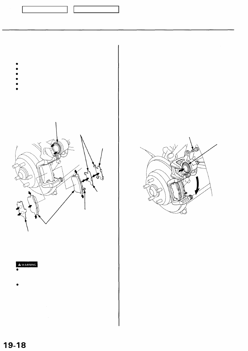
Rear Brake Pads
Inspection and Replacement
Never use an air hose or dry brush to clean brake
assemblies.
Use an OSHA-approved vacuum cleaner to avoid
breathing brake dust.
Block the front wheels before jacking up the rear of
the vehicle.
NOTE: '96 - 98 models shown.
1. Block the front wheels, loosen the rear wheel nuts
slightly, support the rear of the vehicle on safety
stands, then remove the rear wheels.
2. Remove the" brake hose bracket from the trailing arm.
BRAKE HOSE BRACKET
CALIPER BOLT
3.
CALIPER
Remove the caliper bolt, and pivot the caliper up out
of the way. '99 - 01 models only: Hold the caliper pin
with a wrench, being careful not to damage the pin
boot. Remove the caliper bolt with another wrench,
and pivot the caliper up out of the way.
CAUTION:
Thoroughly clean the outside of the caliper to
prevent dust and dirt from entering inside.
Support the caliper with a piece of wire so it
does not hang from the brake hose.
NOTE: Check the hoses and pin boots for damage
and deterioration.
4. Remove the pad shims, pad retainers, and pads.
INNER PAD SHIMS
Check for weakness.
BRAKE PADS
Check for wear.
OUTER PAD SHIM
Check for weakness.
5. Using vernier calipers, measure the thickness of
each brake pad lining.
Brake Pad Thickness:
Standard: 8.5-9.5 mm (0.33-0.37 in)
Service Limit: 1.6 mm (0.06 in)
BACKING PLATE
NOTE: Measurement does not include pad backing
plate thickness.
6. If the brake pad thickness is less than the service
limit, replace the rear pads as a set.
7. Clean the caliper thoroughly; remove any rust, and
check for grooves and cracks.
8. Check the brake disc for damage and cracks.
9. Install the pad retainers.
PAD RETAINERS
Check for weakness.
CALIPER BRACKET
Check for cracks.
Main Menu
Table of Contents
Rear Brake Pads
Inspection and Replacement (cont'd)
10. Apply grease to the points indicated by the arrows
in the following illustration:
Piston end and inner shim B contact surface
Inner shim A contact surface (both sides)
Pads and caliper bracket contact surface
Outer pad and caliper body contact surface
Outer pad shim and outer pad contact surface
Outer pad shim and caliper body contact surface
NOTE: Use the pad grease included in the pad set
or Molykote M77 grease, and apply a thin coat of
grease evenly to the designated points.
PISTON
Apply Molykote M77
to both sides of shims.
INNER SHIM B
INNER SHIM A
WEAR INDICATOR
Install inner pad with its
wear indicator downward.
BRAKE PADS
OUTER PAD SHIM
Apply Molykote M77
to both sides of shim.
11. Install the brake pads and pad shims correctly.
When reusing the pads, always reinstall the
brake pads in their original positions to prevent
loss of braking efficiency.
Contaminated brake discs or pads reduce stop-
ping ability. Keep grease off the discs and pads.
NOTE: Install the pad with the wear indicator on
the inside.
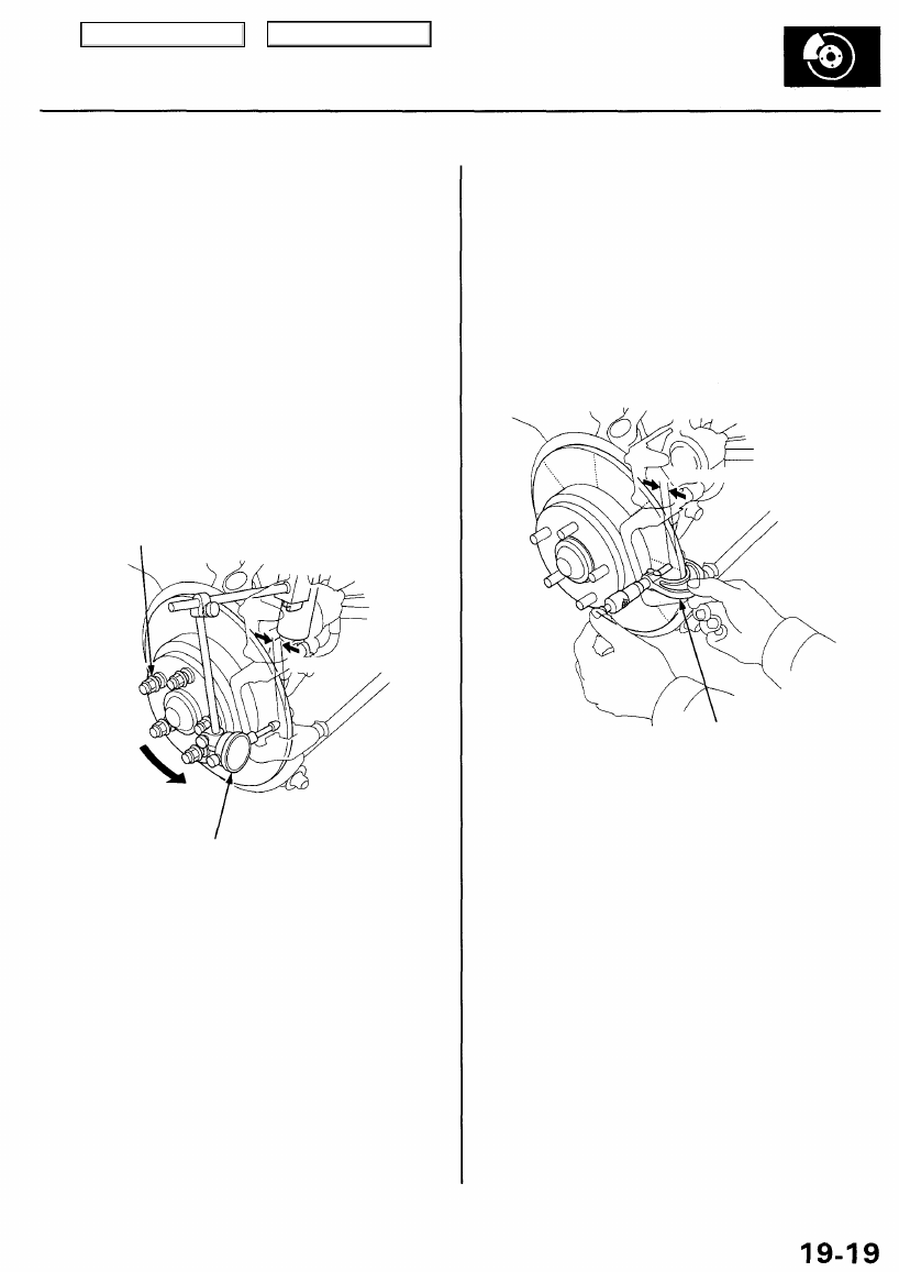
12. Push in the piston so that the caliper will fit over the
pads. Make sure the piston boot is in position to
prevent damaging it when pivoting the caliper
down.
13.
Pivot the caliper down into position, then install the
caliper bolt and tighten it. '99 - 01 models only: Hold
the caliper pin with a wrench, being careful not to
damage the pin boot. Install the caliper bolt with
another wrench, and torque the caliper bolt to the
proper specification.
CAUTION: Be careful not damage the pin boot
when pivoting the caliper down.
CALIPER BOLT
23 N-m (2.3 kgf-m, 17 Ibf-ft)
PISTON
14. Install the brake hose bracket on the trailing arm.
NOTE: Inspect the brake hose for interference and
twisting.
15. Press the brake pedal several times to make sure
the brakes work, then test-drive.
NOTE: Engagement of the brake may require a
greater pedal stroke immediately after the brake
pads have been replaced as a set. Several applica-
tions of the brake pedal will restore the normal
pedal stroke.
16. After installation, check for leaks at hose and line
joints or connections, and retighten if necessary.
Main Menu
Table of Contents
Rear Brake Disc
Disc Runout Inspection
1. Loosen the rear wheel nuts slightly, then raise the
vehicle and make sure it is securely supported.
Remove the rear wheels.
2. Remove the brake pads (see page
).
3. Inspect the disc surface for damage and cracks.
Clean the disc thoroughly, and remove all rust.
4. Use wheel nuts and suitable plain washers to hold
the disc securely against the hub, then mount a dial
indicator as shown, and measure the runout at 10 mm
(0.4 in) from the outer edge of the disc.
Brake Disc Runout:
Service Limit: 0.15 mm (0.006 in)
WHEEL NUT AND
PLAIN WASHER
108 N-m
(11 kgf-m, 80 Ibf-ft)
DIAL INDICATOR
5. If the disc is beyond the service limit, refinish the brake
disc.
Max. Refinishing Limit: 7.5 mm (0.30 in)
'96 - 98 models:
7.5 mm (0.30 in)
'99 - 01 models:
10.0 mm (0.39 in)
NOTE: A new disc should be refinished if its runout
is greater than 0.15 mm (0.006 in).
Disc Thickness and Parallelism
Inspection
1. Loosen the rear wheel nuts slightly, then raise the
vehicle, and make sure it is securely supported.
Remove the rear wheels.
2. Remove the brake pads (see page
).
3. Using a micrometer, measure disc thickness at
eight points, approximately 45° apart and 10 mm
(0.4 in) in from the outer edge of the disc.
MICROMETER
Brake Disc Thickness:
'96 - 98 models:
Standard: 8.9 - 9.1 mm
(0.350 - 0.358 in)
Max. Refinishing Limit: 7.5 mm (0.30 in)
'99 - 01 models:
Standard: 11.9-12.1 mm
(0.469 - 0.476 in)
Max. Refinishing Limit: 10.0 mm (0.39 in)
NOTE: Replace the brake disc if the smallest mea-
surement is less than the max. refinishing limit.
Brake Disc Parallelism: 0.015 mm
(0.0006 in) max.
NOTE: This is the maximum allowable difference
between the thickness measurements.
4. If the disc is beyond the service limit for parallelism,
refinish the brake disc.
for brake disc replacement.
10 mm (0.4 in)
10 mm (0.4 in)
Main Menu
Table of Contents
Нет комментариевНе стесняйтесь поделиться с нами вашим ценным мнением.
Текст