Acura RL (1996-2004 year). Manual — part 482
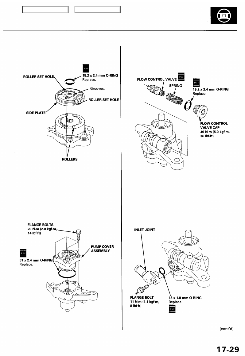
10. Install the side plate on the cam ring by aligning the
roller set holes in the side plate with the rollers.
11. Coat the O-ring with power steering fluid, and posi-
tion it into the pump housing.
15. Coat the O-ring with power steering fluid, and
install it on the flow control valve cap.
16. Install the flow control valve cap on the pump hous-
ing, and tighten it.
17. Coat the O-ring with power steering fluid, and install
it into the grooves in the inlet joint.
18. Install the inlet joint on the pump housing.
12. Install the pump cover assembly in the pump housing.
13. Coat the flow control valve with power steering
fluid.
14. Install the flow control valve and spring on the pump
housing.
9. Coat the O-ring with power steering fluid, and
install it into the grooves in the side plate.
Main Menu
Table of Contents
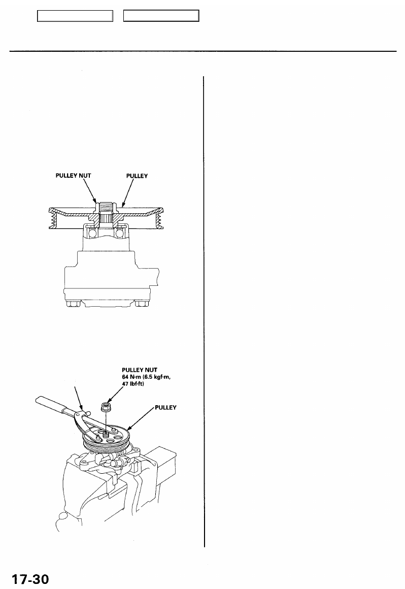
21. Check that the pump turns smoothly by turning the
pulley by hand.
20. Hold the pulley with the special tool, and tighten the
pulley nut.
UNIVERSAL HOLDER
Reassembly (cont'd)
19. Install the pulley as shown below, then loosely
install the pulley nut. Hold the steering pump in a
vise with soft jaws.
CAUTION: Be careful not to damage the pump hous-
ing with the jaws of the vise.
Power Steering Pump
Main Menu
Table of Contents
Removal
NOTE: Using solvent and a brush, wash any oil and dirt
off the valve body unit its lines, and the end if the gear-
box. Blow dry with compressed air.
1. Drain the power steering fluid as described on page
2. Raise the front of vehicle, and support it on safety
stands in the proper locations (see
).
3. Remove the front wheels.
4. Remove the driver's airbag assembly and steering
).
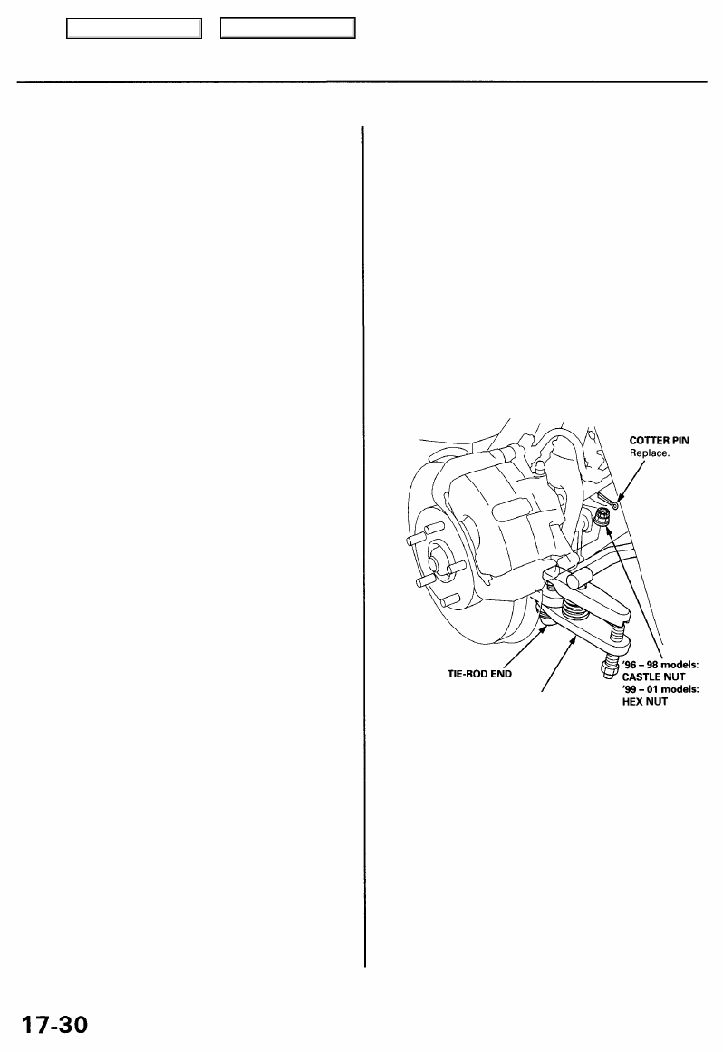
5. Remove the cotter pin from the tie-rod ball joint nut,
and remove the nut.
Power Steering Gearbox
6. Install the 12 mm hex nut on the ball joint.
Be sure that the 12 mm hex nut is flush with the ball
joint pin end, or the threaded section of the ball
joint pin might be damaged by the special tool.
NOTE: Remove the ball joint using the special tool.
Refer to
for how to use the ball joint
remover.
7. Separate the tie-rod ball joint and knuckle using the
special tool.
CAUTION: Avoid damaging the ball joint boot.
BALL JOINT REMOVER,
28 mm
Main Menu
Table of Contents
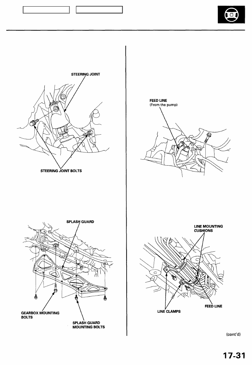
8. Remove the steering joint bolts, then disconnect the
steering joint by moving the joint toward the column.
10. Disconnect the feed line from the valve body unit
upper side.
CAUTION: After disconnecting the feed line, plug or
seal the line fitting with a piece of tape or equivalent
to prevent foreign materials from entering the valve
body unit.
11. Remove the clamps from the line mounting cush-
ions, then remove the feed line from the cushions.
9. Remove the splash guard.
Main Menu
Table of Contents
Нет комментариевНе стесняйтесь поделиться с нами вашим ценным мнением.
Текст