Acura RL (1996-2004 year). Manual — part 457
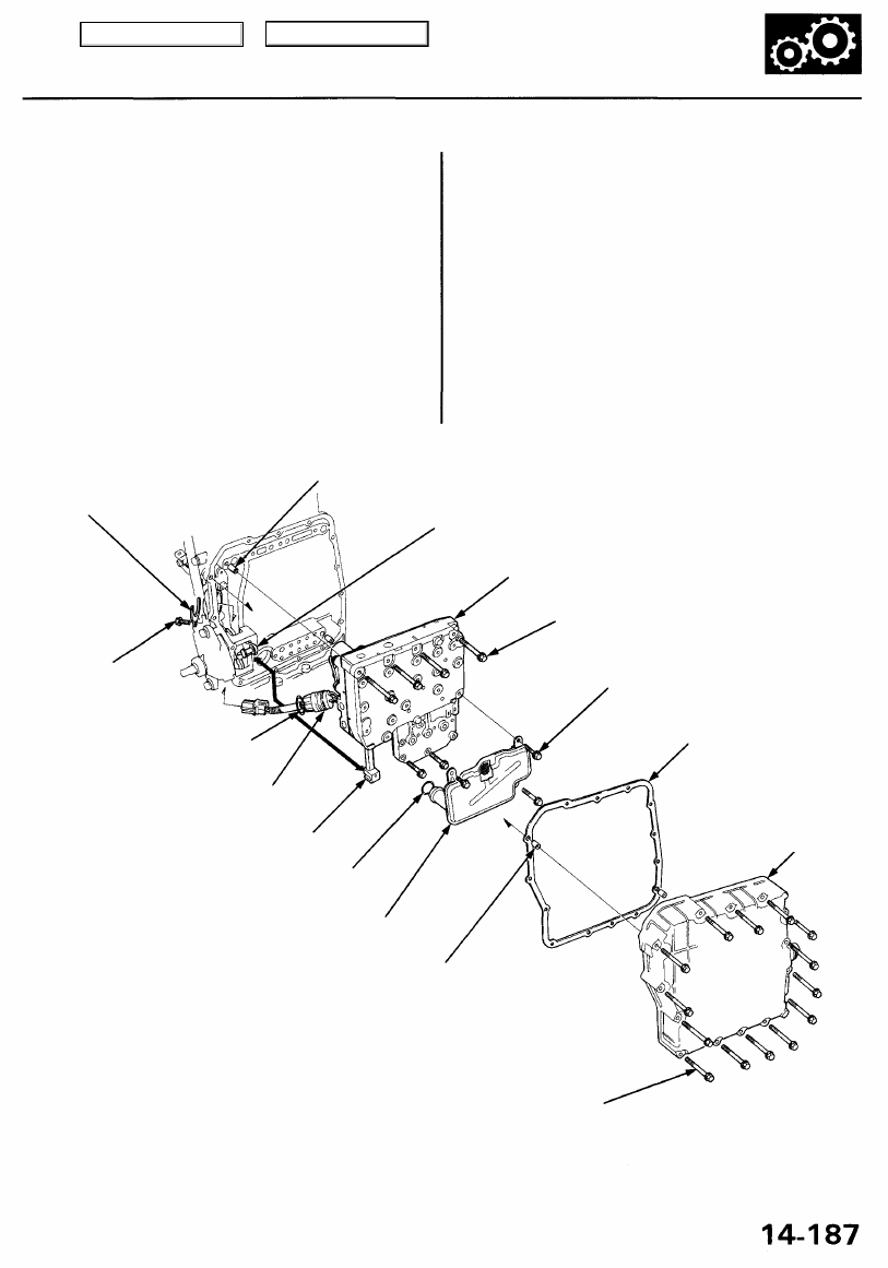
43. Assemble the lower valve body assembly (see page
).
44. Pass the shift solenoid valve/A/T clutch pressure con-
trol solenoid valve harness through the transmission
housing, and put the manual valve and the detent
lever together. Then install the lower valve body
assembly (six bolts) with two dowel pins in the trans-
mission housing.
45. Install the ATF strainer (three bolts).
46. Position the connector stop in the groove on the shift
solenoid valve/A/T clutch pressure control solenoid
valve harness connector, then tighten the bolt.
47. Install the ATF pan with two dowel pins and a new
gasket (14 bolts).
48. Install the ATF cooler lines with new sealing wash-
ers, then tighten the line bolts.
49. Connect the transmission sub-harness connector to
speed sensor connectors and solenoid connectors.
50. Install the transmission range switch harness clamp
to the bracket on the rear cover.
DOWEL PIN
CONNECTOR
STOP
DETENT LEVER
LOWER VALVE BODY
ASSEMBLY
6 x 1.0 mm
12 N-m (1.2 kgf-m,
8.7 Ibf-ft)
O-RING
Replace.
SHIFT SOLENOID
VALVE/A/T CLUTCH PRESSURE
CONTROL SOLENOID VALVE
HARNESS CONNECTOR
6 x 1.0 mm
12 N-m (1.2 kgf-m, 8.7 Ibf-ft)
6 x 1.0 mm
12 N-m (1.2 kgf-m, 8.7 Ibf-ft)
GASKET
Replace.
MANUAL VALVE
ATF PAN
O-RING
Replace.
ATF STRAINER
DOWEL PIN
6 x 1.0 mm
12 N-m (1.2 kgf-m,
8.7 Ibf-ft)
Main Menu
Table of Contents
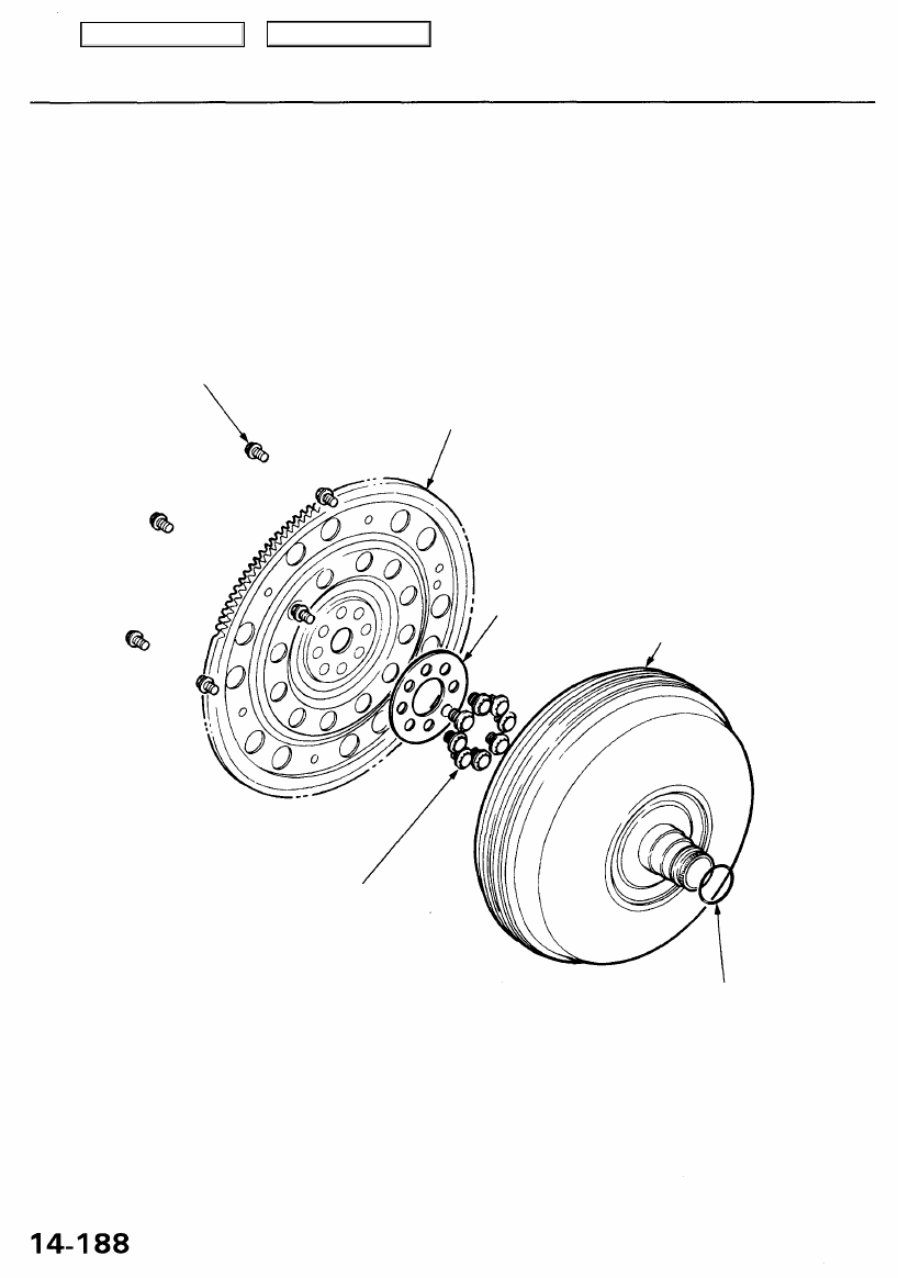
Torque Converter/Drive Plate/Ring Gear
8 x 1.25 mm
22 N-m
(2.2 kgf-m, 16 Ibf-ft)
DRIVE PLATE/RING GEAR
TORQUE CONVERTER
ASSEMBLY
12 x 1.0 mm
74 N-m
(7.5 kgf-m, 54 Ibf-ft)
Torque in a crisscross pattern
O-RING
Replace.
WASHER
Main Menu
Table of Contents
Transmission
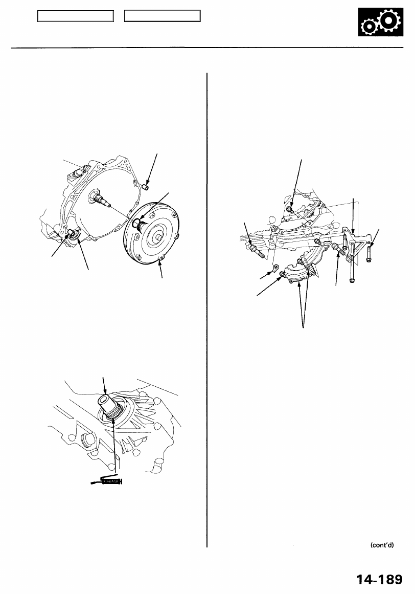
Installation
1. Flush the ATF cooler (see pages
and
).
2. Install the torque converter securely with a new O-ring
on the mainshaft, and install two 14 x 20 mm dowel
pins in the torque converter housing.
14 x 20 mm
DOWEL PIN
O-RING
Replace.
14 x 20 mm
DOWEL PIN
EXTENSION
SHAFT
TORQUE
CONVERTER
3. Clean the extension shaft opening on the differen-
tial side.
4. Insert the extension shaft in its opening, and apply
Super High Temp Urea Grease (P/N 08798 - 9002) to
the shaft splines.
EXTENSION SHAFT
5. Place the transmission on a jack, and raise it to
engine level.
6. Attach the transmission to the engine, then install
the transmission housing mounting bolt with the
26 mm shim.
NOTE: Do not install the transmission housing bolt
on the engine stiffener side.
8 x 1.25 mm
22 N-m (2.2 kgf-m, 16 Ibf-ft)
ENGINE
STIFFENER
12 x 1.25 mm
64 N-m (6.5 kgf-m,
47 Ibf-ft)
8 x 1.25 mm
22 N-m
(2.2 kgf-m,
16 Ibf-ft)
26 mm SHIM
6 x 1.0 mm
12 N-m (1.2 kgf-m,
8.7 Ibf-ft)
TRANSMISSION HOUSING
MOUNTING BOLT
12 x 1.25 mm
64 N-m (6.5 kgf-m, 47 Ibf-ft)
TORQUE CONVERTER
COVERS
7. Attach the torque converter to the drive plate with
six bolts and torque:
Rotate the crankshaft as necessary to tighten the
bolts to 1/2 of the specified torque, then to the final
torque, in a crisscross pattern. After tightening the
last bolt, check that the crankshaft rotates freely.
8. Install the torque converter covers.
9. Install the engine stiffener. Tighten the engine stiff-
ener 8 mm bolts loosely, and tighten the transmis-
sion housing mounting bolt to the specified torque,
then tighten the 8 mm bolts to the specified torque.
SUPER HIGH TEMP
UREA GREASE
(P/N 08798 -9002)
Main Menu
Table of Contents
Transmission
Installation (cont'd)
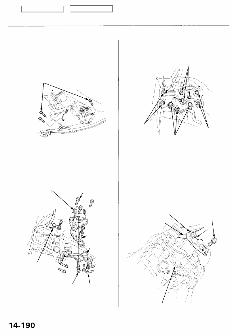
10. Install the transmission housing mounting bolts
from the transmission side.
TRANSMISSION HOUSING
MOUNTING BOLTS
12 x 1.25 mm
64 N-m (6.5 kgf-m, 47 Ibf-ft)
11. Install the transmission beam to the rear transmis-
sion mount bracket/mount. Tighten the three center
bolts loosely, then install them with the exhaust
pipe bracket on the rear cover and body.
EXHAUST PIPE
BRACKET
TRANSMISSION
BEAM
SHIFT CABLE
GUIDE BRACKET
TRANSMISSION
BEAM CENTER BOLTS
10 x 1.25 mm
Loosely install.
12. Tighten the transmission beam outer bolts (four
bolts).
13. Tighten the rear transmission mount bracket bolts
(three bolts).
14. Tighten the transmission beam center bolts (three
bolts) installed loosely in step 11.
15. Remove the transmission jack from the transmis-
sion.
16. Install the shift cable guide bracket on the transmis-
sion beam.
SHIFT CABLE GUIDE
BRACKET
TRANSMISSION BEAM
6 x 1.0 mm
9.8 N-m (1.0 kgf-m,
7.2 Ibf-ft)
SHIFT CABLE
TRANSMISSION
BEAM BOLTS
10 x 1.25 mm
REAR TRANSMISSION
MOUNT BRACKET/
MOUNT
REAR TRANSMISSION MOUNT
BRACKET BOLTS
10 x 1.25 mm
38 N-m (3.9 kgf-m, 28 Ibf-ft)
TRANSMISSION BEAM
CENTER BOLTS
10 x 1.25 mm
38 N-m (3.9 kgf-m, 28 Ibf-ft)
TRANSMISSION
BEAM OUTER BOLT
10 x 1.25 mm
38 N-m
(3.9 kgf-m,
28 Ibf-ft)
TRANSMISSION
BEAM OUTER BOLTS
10 x 1.25 mm
38 N-m (3.9 kgf-m,
28 Ibf-ft)
REAR TRANSMISSION
MOUNT BRACKET BOLTS
10 x 1.25 mm
38 N-m
(3.9 kgf-m, 28 Ibf-ft)
Main Menu
Table of Contents
Нет комментариевНе стесняйтесь поделиться с нами вашим ценным мнением.
Текст