Acura RL (1996-2004 year). Manual — part 242
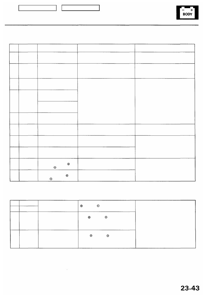
Cavity Wire
Test condition
Test: Desired result
Possible cause if result is not obtained
1
8
7
13
11
15
4
4
14
3
12
BLK
GRN/WHT
WHT/BLK
BLU/WHT
YEL/GRN
BLU/ORN
BLU/GRN
BLU/GRN
BLU/ORN
RED
GRN
Under all conditions
Under all conditions
Ignition switch ON (II)
Ignition switch ON (II) and
driver's window switch
UP
Ignition switch ON (II) and
driver's window switch
AUTO UP
Ignition switch ON (II) and
driver's window switch
AUTO DOWN
Ignition switch ON (II) and
driver's window switch
DOWN
Driver's window switch
DOWN
Driver's window switch
OFF
Driver's window switch
OFF
Connect the battery
power to the No. 12
and No. 3 terminals
Connect the battery
power to the No. 3 and
No. 12 terminals
Check for continuity to ground:
There should be continuity.
Check for voltage to ground:
There should be battery voltage.
Check for voltage to ground:
There should be battery voltage.
Check for voltage to ground:
There should be battery voltage.
Check for continuity to ground:
There should be continuity.
Check for continuity between the No. 4
and No. 14 terminals:
There should be continuity.
Check for continuity between the No. 4
and No. 14 terminals:
There should be continuity.
Check the driver's window motor:
It should run (the window moves
down).
Check the driver's window motor:
It should run (the window moves up).
• Poor ground (G251)
• An open in the wire
• Blown No. 41 (20 A) fuse in the under-
hood fuse/relay box
• An open in the wire
• Blown No. 17 (7.5 A) [No. 23 (7.5 A)] fuse
in the under-dash fuse/relay box
• Faulty power window relay
• An open in the wire
• Faulty power window master switch
• An open in the wire
• Faulty power window master switch
• Poor ground (G251)
• An open in the wire
• Faulty power window master switch
• An open in the wire
• Faulty power window motor
• An open in the wire
Reconnect the connector to the power window control unit.
Cavity Wire
Test condition
Test: Desired result
Possible cause if result is not obtained
17
9
5
16
GRN/YEL
YEL/BLU
GRN/RED
YEL/WHT
Ignition switch ON (II)
While operating the driv-
er's window switch
While operating the driv-
er's window switch
Check for voltage between the No. 17
and No. 9 terminals:
There should be battery voltage.
Check for pulse voltage between the
No. 5 and No. 9 terminals:
There should be pulse voltage (the
voltmeter needle should move back
and forth alternately).
Check for pulse voltage between the
No. 16 and No. 9 terminals:
There should be pulse voltage (the
voltmeter needle should move back
and forth alternately).
• Faulty power window motor
• Faulty pulser
• An open in the wire
Main Menu
Table of Contents
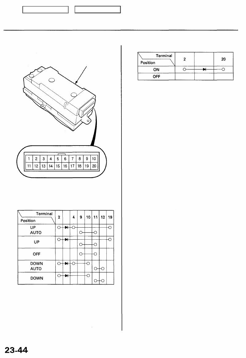
Power Windows
Driver's Window Switch Test
1. Remove the power window master switch.
POWER WINDOW
MASTER SWITCH
2. Check for continuity between the terminals in each
switch position according to the tables.
Driver's window switch
Main switch
Main Menu
Table of Contents
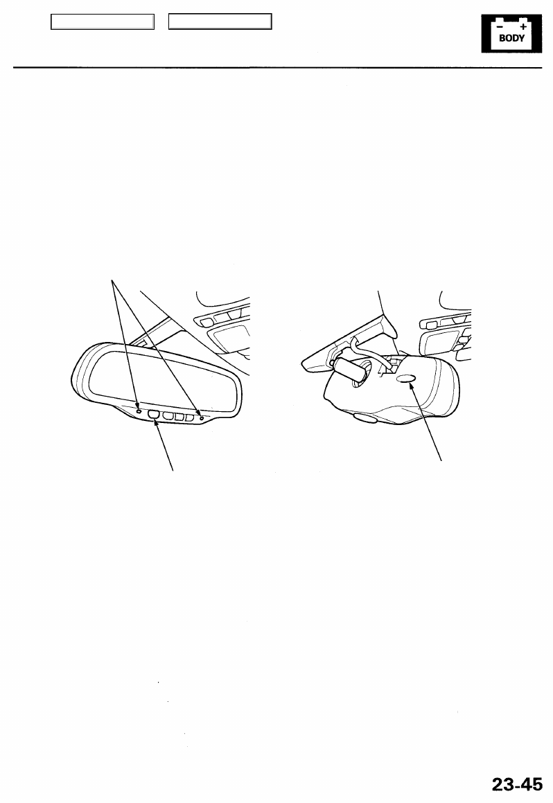
Automatic Inside Dimming Mirror
Description ('02-04 Model USA)
The automatic dimming has a front-facing lux level sensor, a rear-facing lux level sensor, and a control unit. The control
unit receives signals from each sensor. Based on the difference between the two lux levels (the light outside the vehicle
and the light from the headlights of the other vehicle, etc.), the control unit controls the electro-chromic gel to reduce the
glare. This dimming function is canceled when the transmission is in reverse, or when the automatic inside dimming mir-
ror switch is turned OFF.
BACKWARD LUX
LEVEL SENSOR
SWITCH
FORWARD LUX
LEVEL SENSOR
Main Menu
Table of Contents
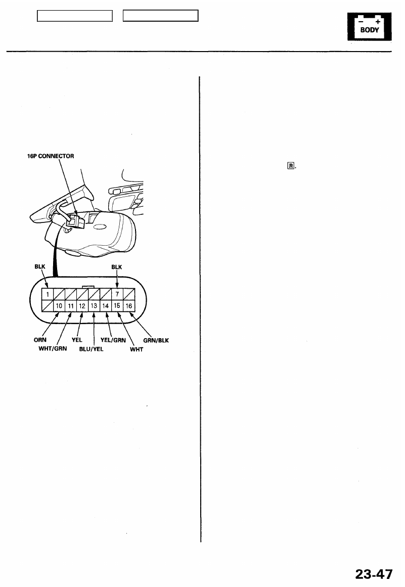
Test/Replacement ('02-04 Model USA)
NOTE: Before testing, check the No. 13 (7.5 A) fuse. No.
7, 10, 11, 13, 14 and 15 terminals are OnStar switches
microphone power, ground and signal lines.
1. Disconnect the 16P connector from the mirror.
2. Check for voltage between the No. 12 terminal and
body ground with the ignition switch ON (II).
• If there is battery voltage, go to step 3.
• If there is no voltage, check for:
— an open in the wire, or
— poor ground (G401, G402).
3. Check for voltage between the No. 16 terminal and
body ground with the ignition switch ON (II) and
A/T gear position in
• If there is battery voltage, replace the mirror by
removing torx screw.
• If there is no voltage, check for:
— an open in the wire, or
— faulty reverse relay, or
— faulty transmission range switch, or
— faulty diode.
Wire side of
female terminals
Main Menu
Table of Contents
Нет комментариевНе стесняйтесь поделиться с нами вашим ценным мнением.
Текст