Acura RL (1996-2004 year). Manual — part 387
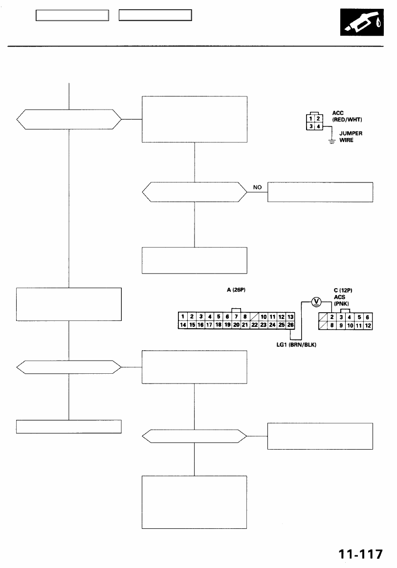
Is there a clicking noise from
the A/C compressor clutch?
NO
YES
Check for an open in the wire
(ACC line):
Momentarily connect the A/C
clutch relay connector terminal
No. 4 to body ground with a
jumper wire several times.
A/C CLUTCH RELAY CONNECTOR (C344)
Wire side of
female terminals
Is there a clicking noise from
the A/C compressor clutch?
See air conditioner inspection
(see
).
YES
Repair open in the wire between
the PCM (A8) and the A/C clutch
relay.
PCM CONNECTORS
Check the A/C operation:
1. Start the engine.
2. Turn the blower switch ON.
3. Turn the A/C switch ON.
Does the A/C operate?
YES
Check for an open in the wire
(ACS line):
Measure voltage between PCM
connector terminals A26 and C2.
Air conditioning signal is OK.
Wire side of female terminals
Is voltage less than 1.0 V?
YES
Repair open in the wire between
the PCM (C2) and the radiator fan
control unit.
— Substitute a known-good PCM
for immobilizer information).
If symptom/indication goes
away, replace the original PCM.
— See the air conditioner inspec-
tion (see
NO
NO
Main Menu
Table of Contents
Idle Control System
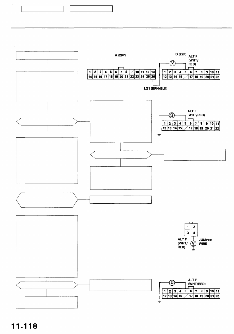
Alternator (ALT) FR Signal
PCM CONNECTORS
Is there about 5 V?
YES
Check the operation of the ALT:
1. Turn the ignition switch OFF.
2. Reconnect the ALT GRN 4P
connector to the ALT.
3. Start the engine. Hold the
engine at 3,000 rpm with no
load (in Park or neutral) until
the radiator fan comes on,
then let it idle.
4. Measure voltage between PCM
connector terminals D5 and A26.
Does the voltage decrease when
headlights and rear defogger are
turned on?
NO
Check for an open in the wire (ALT
F line):
1. Turn the ignition switch OFF.
2. Disconnect the negative bat-
tery cable from the battery.
3. Disconnect the PCM connec-
tor D (22P).
4. Disconnect the GRN 4P con-
nector from the ALT.
5. Connect the ALT 4P connector
terminal No. 4 to body ground
with a jumper wire.
6. Check for continuity between
body ground and PCM con-
nector terminal D5.
Is there continuity?
YES
).
NO
Wire side of female terminals
Check for a short in the wire (ALT
F line):
1. Turn the ignition switch OFF.
2. Disconnect the negative bat-
tery cable from the battery.
3. Disconnect the PCM connector
D (22P).
4. Check for continuity between
body ground and PCM con-
nector terminal D5.
Is there continuity?
Repair short in the wire between
the PCM (D5) and the ALT.
NO
Substitute a known-good PCM
and recheck (see page
for
immobilizer information). If pre-
scribed voltage is now available,
replace the original PCM.
ALT FR signal is OK.
ALT GRN 4P CONNECTOR (C131)
Repair open wire between the
PCM (D5) and the ALT.
PCM CONNECTOR D (22P)
Wire side of female terminals
NO
Wire side of female terminals
YES
YES
This signals the PCM when the Alternator (ALT) is charging.
Inspection of ALT FR Signal.
Check for a short in the wire (ALT
F line):
1. Disconnect the GRN 4P con-
nector from the ALT.
2. Turn the ignition switch ON (II).
3. Measure voltage between PCM
connector terminals D5 and A26.
Main Menu
Table of Contents
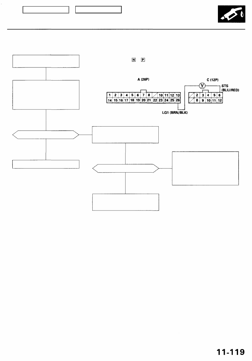
PCM CONNECTORS
Wire side of female terminals
Is there battery voltage?
Is the fuse OK?
NO
— Repair short in the wire be-
tween the PCM (C6) and the
No. 14 STARTER SIGNAL (7.5
A) fuse or the PGM-FI main
relay.
— Replace the No. 14 STARTER
SIGNAL (7.5 A) fuse.
Repair open in the wire between
the PCM (C6) and the No. 14
STARTER SIGNAL (7.5 A) fuse.
YES
Inspect the No. 14 STARTER SIG-
NAL (7.5 A) fuse in the under-dash
fuse/relay box.
NO
YES
Starter switch signal is OK.
Check for an open or short in the
wire (STS line):
Measure voltage between PCM
connector terminals C6 and A26
with the ignition switch in the
start position (III).
NOTE: Transmission in or position.
Inspection of Starter Switch Sig-
nal.
This signals the PCM when the engine is cranking.
Starter Switch Signal
Main Menu
Table of Contents
Idle Control System
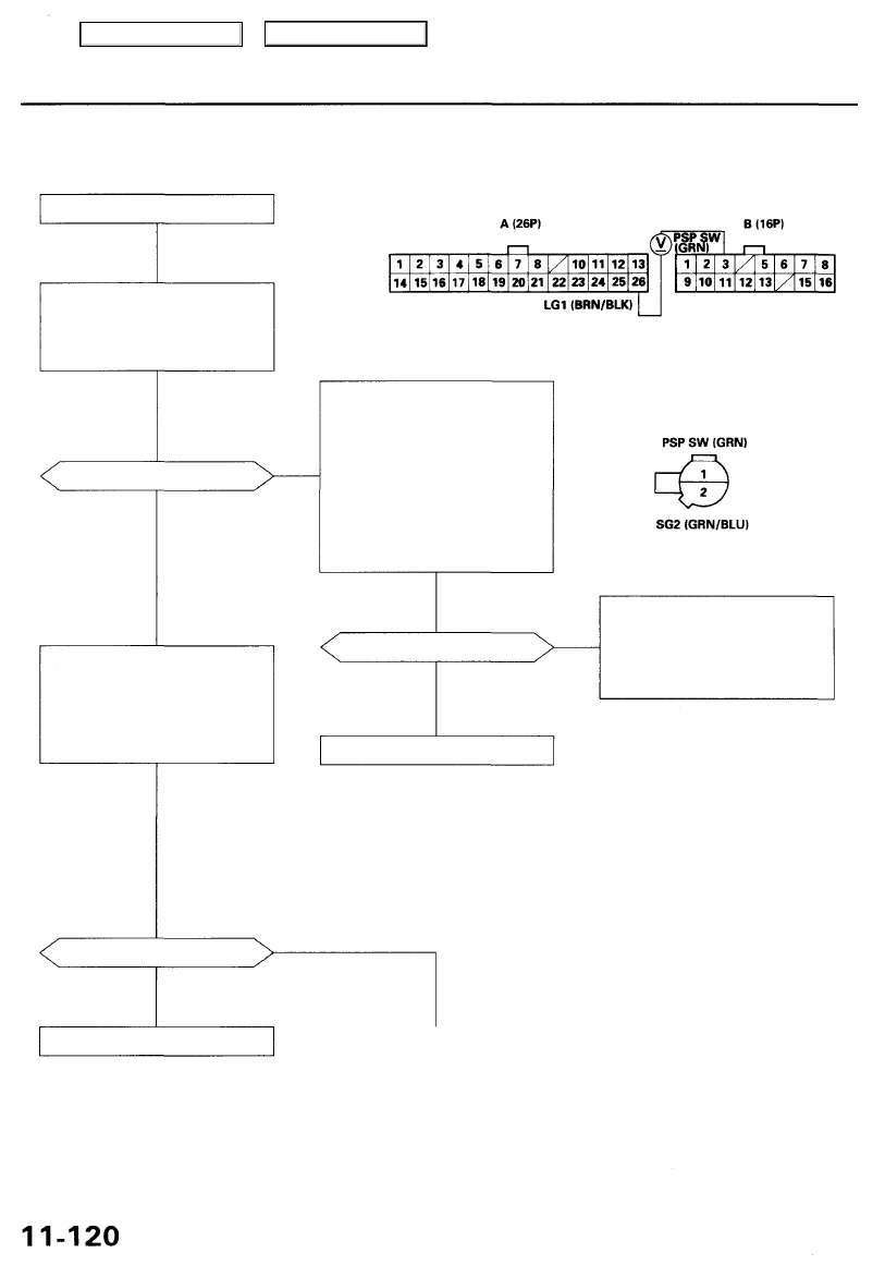
Power Steering Pressure (PSP) Switch Signal
This signals the PCM when the power steering load is high.
Inspection of PSP switch signal.
Check for an open in the wire (PSP
SW line):
1. Turn the ignition switch ON (II).
2. Measure voltage between PCM
connector terminals B3 and A26.
Is there less than 1.0V?
NO
YES
Check the operation of the PSP
switch:
1. Start the engine.
2. Turn steering wheel to full
lock.
3. Measure voltage between PCM
connector terminals B3 and A26.
Is there battery voltage?
NO
PCM CONNECTORS
Check for an open in the wire (PSP
SW Iine):
1. Turn the ignition switch OFF.
2. Disconnect the PSP switch
connector.
3. Turn the ignition switch ON (II).
4. At the wire side, connect the
PSP switch connector termi-
nals No. 1 and No. 2 with a
jumper wire.
5. Measure voltage between PCM
connector terminals B3 and A26.
Wire side of female terminals
PSP SWITCH CONNECTOR (C120)
JUMPER
WIRE
Wire side of female terminals
Is there less than 1.0V?
NO
— Repair open in the wire be-
tween the PCM (B3) and the
PSP switch.
— Repair open in wire between
the PCM (D22) and the PSP
switch.
PSP switch signal is OK.
YES
Replace the PSP switch.
YES
Main Menu
Table of Contents
Нет комментариевНе стесняйтесь поделиться с нами вашим ценным мнением.
Текст