Acura RL (1996-2004 year). Manual — part 492
Front Suspension
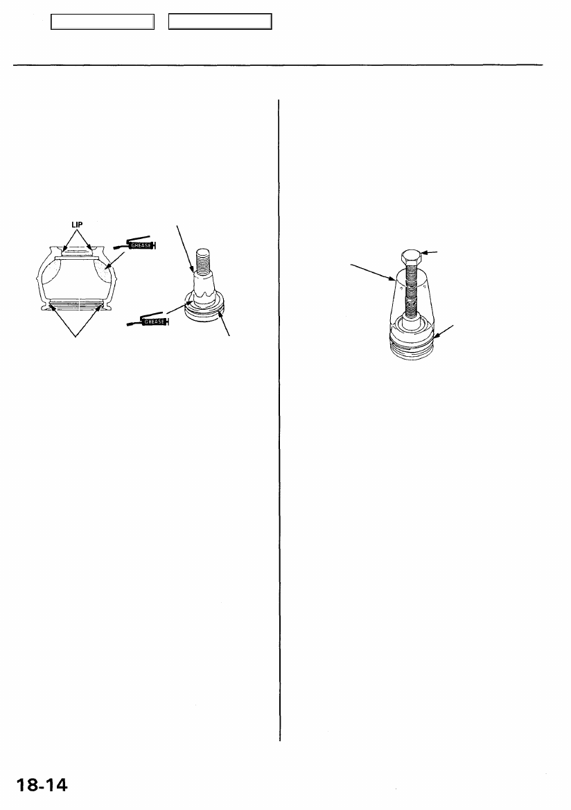
Ball Joint Boot Replacement
1. Remove the set ring and the boot
CAUTION: Do not contaminate the boot installation
section with grease.
2. Pack the interior of the boot and lip with grease.
BALL PIN TAPERED SECTION
3. Wipe the grease off the sliding surface of the ball
pin, and pack with fresh grease.
CAUTION:
• Keep grease off the boot installation section and
the tapered section of the ball pin.
• Do not allow dust, dirt, or other foreign materi-
als to enter the boot.
4. Install the boot in the groove of the boot installation
section securely, then bleed air.
5. Install the upper and lower ball joint boot set rings
using the special tools as follows:
Adjust the special tool with the adjusting bolt until
the end of the tool aligns with the groove on the
boot. Slide the set ring over the tool and into posi-
tion.
BALL JOINT
BOOT CLIP
GUIDE
ADJUSTING BOLT
Adjust the depth by
turning the bolt.
SET RING
CAUTION: After installing the boot, check the ball
pin tapered section for grease contamination, and
wipe it if necessary.
BOOT INSTALLATION SECTION
Wipe off the grease.
BOOT INSTALLATION SECTION
Wipe off the grease.
Main Menu
Table of Contents
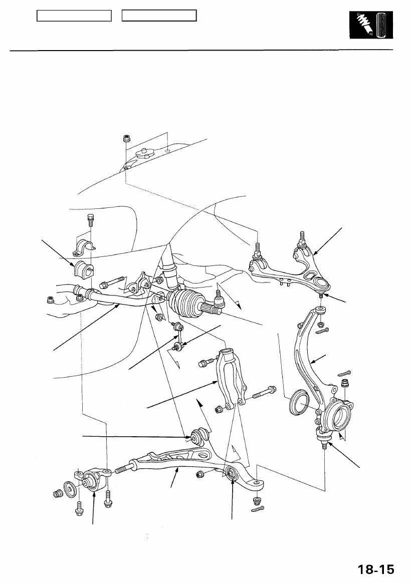
Suspension Arms Removal/Inspection
CAUTION:
• Replace the self-locking nuts after removal.
• Be careful not to damage the ball joint boot.
STABILIZER END
RUBBER BUSHING
Check for deterioration
and damage.
UPPER ARM ASSEMBLY
Check for damage.
STABILIZER BAR
Check for bending and
damage.
BALL JOINT
Inspect for faulty
movement and wear.
BALL JOINT BOOT
Check for deterioration
and damage.
KNUCKLE
Check for damage.
LOWER ARM
RUBBER BUSHING
Check for deterioration
and damage.
BALL JOINT
Inspect for faulty
movement and wear.
BALL JOINT BOOT
Check for deterioration
and damage.
COMPLIANCE BUSHING
Do not contaminate the
tapered section with oil and
grease.
DAMPER FORK
RUBBER BUSHING
Check for deterioration
and damage.
LOWER ARM ASSEMBLY
Check for damage.
Do not disassemble
as it might deform the plate.
DAMPER
FORK
Do not interchange the
right and left damper fork.
STABILIZER LINK
Inspect for faulty
movement and wear.
BOOT
Check tor deterioration
and damage.
Main Menu
Table of Contents
Front Suspension
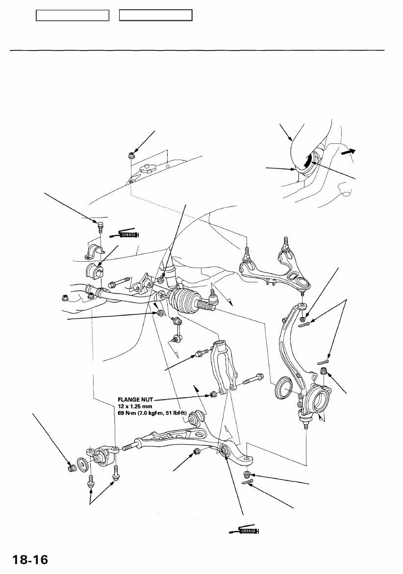
Suspension Arms Installation
NOTE:
• Wipe off the grease before tightening the nut at the ball joint.
• The right and left damper forks are not symmetrical. The left damper fork is marked with "Z5L" while the right damper
fork is marked with "Z5R". Do not interchange them.
STABILIZER BAR
Align the stabilizer mark
with the end of the stabilizer bushing.
FLANGE BOLT
10 x 1.25 mm
'96-98 models:
39 N-m (4.0 kgf-m, 29 Ibf-ft)
'99 - 01 models:
54 N-m
(5.5 kgf-m, 40 Ibf-ft)
CASTLE NUT
10 x 1.25 mm
39 - 47 N-m
(4.0 - 4.8 kgf-m, 29 - 35 Ibf-ft)
COTTER PIN
Replace.
FRONT
MARK
SELF-LOCKING NUT
10 x 1.25mm
'96 - 98 models:
37 N-m (3.8 kgf-m, 27 Ibf-ft)
'99 - 01 models:
43 N-m (4.4 kgf-m, 32 Ibf-ft)
Replace.
Hold the ball joint pin using a hex wrench,
and tighten the self-locking nut.
SELF-LOCKING NUT
12 x 1.25 mm
103 N-m
(10.5 kgf-m, 76 Ibf-ft)
Replace.
FLANGE BOLT
12 x 1.25 mm
113 N-m
(11.5 kgf-m, 83 Ibf-ft)
FLANGE NUT 10 x 1.25 mm
29 N-m (3.0 kgf-m, 22 Ibf-ft)
Before tightening the flange nut,
position the ball joint pin
in the middle of its range of travel,
with the suspension under vehicle load.
RUBBER BUSHING
CASTLE NUT
('96 - 98 models)
12 x 1.25 mm
49 - 59 N-m
(5.0 - 6.0 kgf-m,
36-43 Ibf-ft)
HEX NUT
('99 - 01 models)
54 N-m
(5.5 kgf-m, 40 Ibf-ft)
CASTLE NUT
14 x 2.0 mm
69 - 78 N-m
(7.0 - 8.0 kgf-m, 51 - 58 Ibf-ft)
COTTER PIN
Replace.
SILICONE
SELF-LOCKING NUT
12 x 1.25 mm
64 N-m
(6.5 kgf-m, 47 Ibf-ft)
Replace.
STABILIZER
BUSHING
FLANGE NUT
12 x 1.25 mm
123 N-m
(12.5 kgf-m, 90 Ibf-ft)
STABILIZER HOLDER
RUBBER BUSHING
SILICONE
FLANGE BOLT
10 x 1.25 mm
43 N-m (4.4 kgf-m,
32 Ibf-ft)
Main Menu
Table of Contents
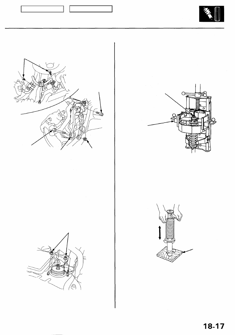
Front Damper
Removal
1. Remove the brake hose clamps from the damper.
BRAKE HOSE
CLAMPS
FLANGE
BOLT
FLANGE BOLT
DAMPER FORK
SELF-LOCKING NUT
12 x 1.25 mm
Replace.
2. Remove the flange bolt.
3. Remove the flange bolt and self-locking nut, then
remove the damper fork.
4. Remove the damper by removing the five flange
nuts.
NOTE: Mark the right and left dampers or store them
separately. Do not confuse them on installation.
FLANGE NUTS
Disassembly/Inspection
Disassembly
1. Compress the damper spring with the spring com-
pressor according to the manufacturer's instructions,
then remove the self-locking nut.
CAUTION: Do not compress the spring more than
necessary to remove the nut.
SELF-LOCKING NUT
10 x 1.25 mm
Replace.
STRUT SPRING
COMPRESSOR:
(Commercially available)
BRANICK® T/N MST-580A, T/N 7200,
or equivalent
2. Remove the damper from the spring compressor,
then disassemble the damper as shown on the next
page.
Inspection
1. Reassemble all parts, except the spring.
2. Push on the damper as shown.
WOODEN
BLOCK
3. Check for smooth operation through a full stroke,
both compression and extension.
NOTE: The damper should move smoothly. If it does
not (no compression or no extension), the gas is
leaking and the damper should be replaced.
4. Check for oil leaks, abnormal noises, or binding dur-
ing these tests.
Main Menu
Table of Contents
Нет комментариевНе стесняйтесь поделиться с нами вашим ценным мнением.
Текст