Acura RL (1996-2004 year). Manual — part 490
Wheel Alignment Wheel/Hub Inspection
Turning Angle Inspection
NOTE: Use commercially-available computerized four
wheel alignment equipment to measure wheel align-
ment (caster, camber, toe, and/or turning angle). Follow
the equipment manufacturer's instructions.
1. Turn the wheel right and left while applying the
brake, and measure the turning angle of both
wheels.
Turning angle:
Inward wheel:
41 °30' ± 2°
Outward wheel: 33°54' (reference)
Bearing End Play
2. If the turning angle is not within the specifications,
check for bent or damaged suspension compo-
nents.
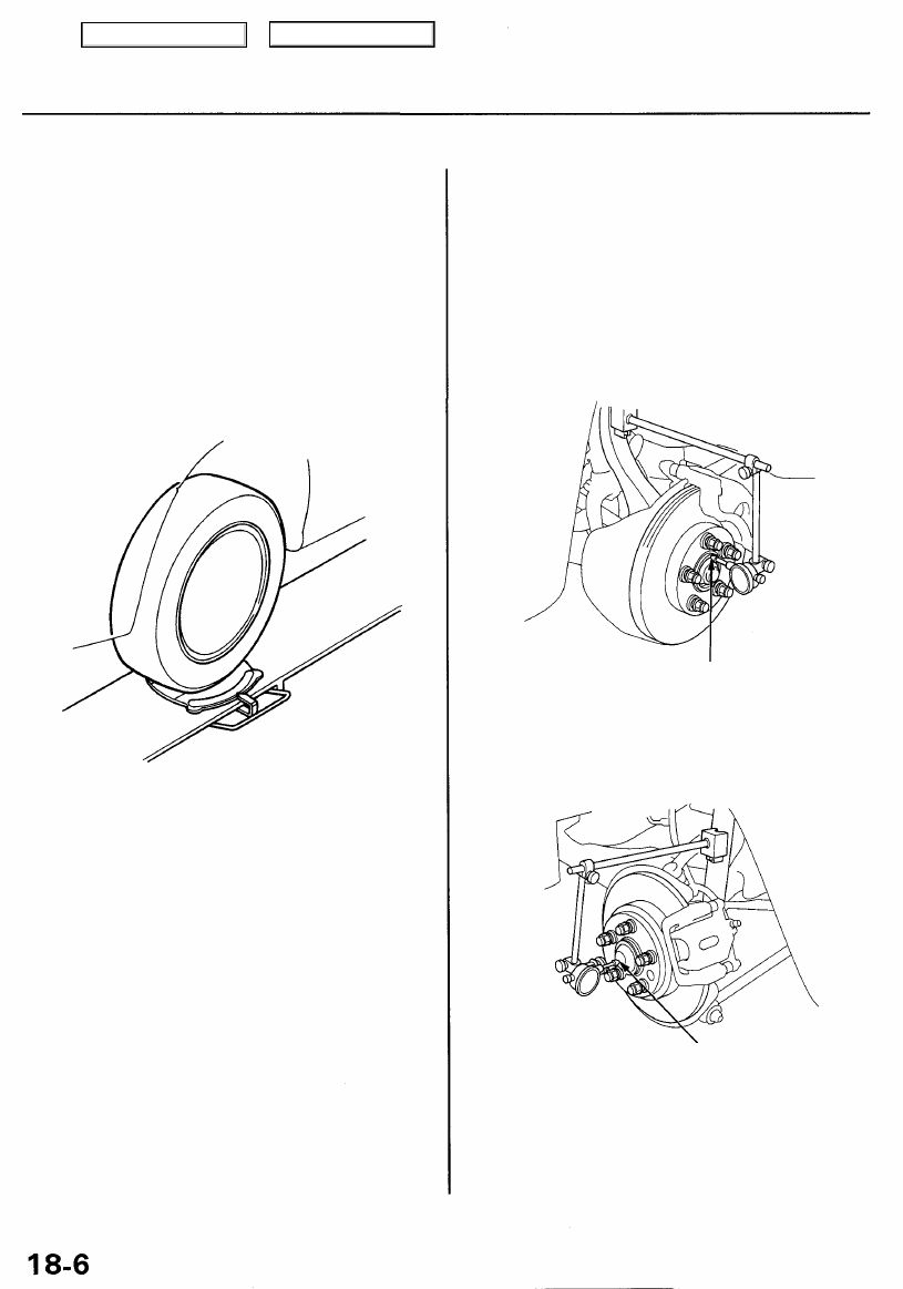
1. Raise the vehicle off the ground, and support it with
safety stands in the proper locations (see
).
2. Remove the wheels, then reinstall the wheel nuts.
3. Attach the dial gauge as shown.
Front/Rear:
Standard: 0 - 0.05 mm (0 - 0.002 in)
Front
Measure the end play at the
hub flange.
Rear
Measure end the play at the center of
the hubcap.
4. Measure the bearing end play by moving the brake
disc inward or outward.
5. If the bearing end play measurement is more than
the standard, replace the wheel bearing.
Main Menu
Table of Contents
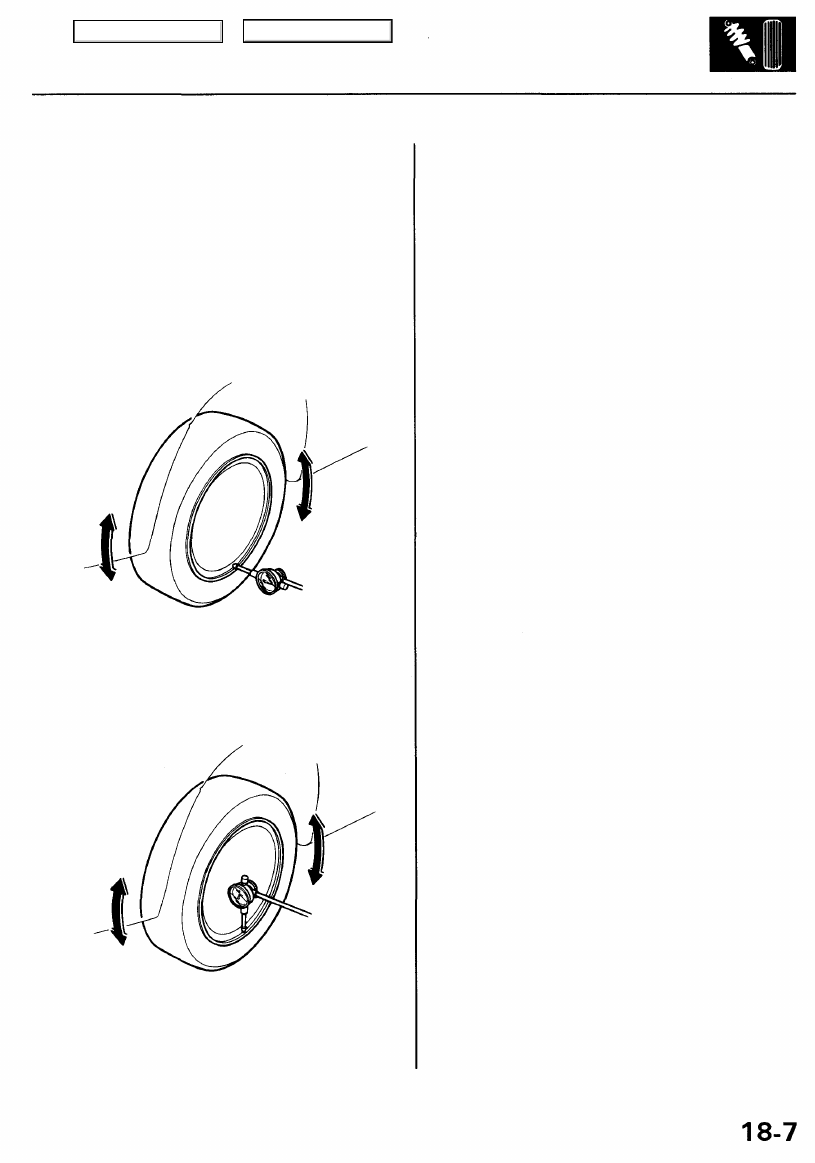
Wheel Runout
1. Raise the vehicle off the ground, and support it with
safety stands in the proper locations (see
).
2. Check for bent or deformed wheels.
3. Attach the dial gauge as shown.
Axial Runout
Standard:
Aluminum Wheel: 0 - 0.7 mm (0 - 0.03 in)
Service Limit: 2.0 mm (0.08 in)
Radial Runout
Standard:
Aluminum Wheel: 0 - 0.7 mm (0 - 0.03 in)
Service Limit: 1.5 mm (0.06 in)
4. Measure the wheel runout by turning the wheel.
5. If the wheel runout is more than the service limit,
replace the wheel.
Main Menu
Table of Contents
Front Suspension
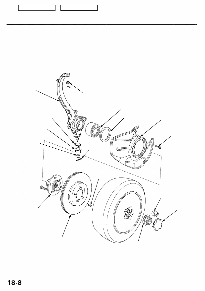
Knuckle/Hub Replacement
NOTE:
• Use only genuine Honda wheel weights for aluminum wheels. Non-genuine wheel weights may corrode and damage
aluminum wheels.
• Before installing the wheel, clean the mating surface of the brake disc and inside of the wheel.
KNUCKLE
WHEEL BEARING
SPLASH GUARD
BALL JOINT BOOT
CASTLE NUT
14 x 2.0 mm
FRONT HUB
Check for damage and
cracks.
BRAKE DISC
Check for wear and
6 mm SCREW
5 N-m
(0.5 kgf-m, 4 Ibf-ft)
WHEEL NUT
12 x 1.5 mm
108 N-m (11 kgf-m, 80 Ibf-ft)
CENTER CAP
SPINDLE NUT
24 x 1.5 mm
245 N-m (25 kgf-m, 181 Ibf-ft)
Replace.
NOTE:
• Before installing the spindle nut, apply
engine oil to the
seating surface of the nut.
• After tightening, use a drift to stake the
spindle nut
shoulder against the spindle.
FLAT-HEAD SCREW
9.8 N-m
(1.0 kgf-m, 7.2 Ibf-ft)
COTTER PIN
Replace.
SNAP RING
CASTLE NUT
10 x 1.25 mm
SET RING
Main Menu
Table of Contents
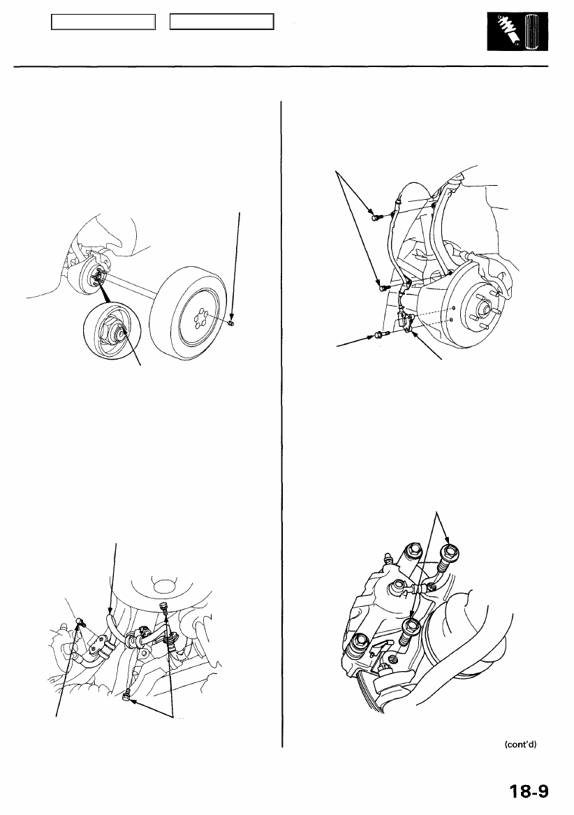
1. Loosen the wheel nuts slightly.
2. Raise the front of the vehicle, and support it with
safety stands in the proper locations (see
3. Remove the wheel nuts and front wheel.
WHEEL NUT
108 N-m
(11 kgf-m, 80 Ibf-ft)
SPINDLE NUT 24 x 1.5 mm
245 N-m
(25 kgf-m, 181 Ibf-ft)
Replace.
NOTE:
• Before installing the spindle nut, apply
engine oil to the seating surface of the nut.
• After tightening, use a drift to stake the
spindle shoulder against the spindle.
4. Raise the locking tab on the spindle nut, then
remove the nut.
5. Remove the brake hose mounting bolts.
BRAKE HOSE
9.8 N-m
(1.0 kgf-m, 7.2 Ibf-ft)
22 N-m
(2.2 kgf-m, 16 Ibf-ft)
6. Remove the wheel sensor from the knuckle.
NOTE: Do not disconnect the wheel sensor connec-
tor.
9.8 N-m (1.0 kgf-m, 7.2 Ibf-ft)
SENSOR MOUNTING
BOLTS
9.8 N-m
(1.0 kgf-m, 7.2 Ibf-ft)
WHEEL SENSOR
7. Remove the caliper bracket mounting bolts, and
hang the caliper assembly to one side.
CAUTION: To prevent accidental damage to the
caliper or brake hose, use a short piece of wire to
hang the caliper from the undercarriage.
CALIPER BRACKET MOUNTING BOLTS
12 x 1.25 mm
108 N-m (11 kgf-m, 80 Ibf-ft)
Main Menu
Table of Contents
Нет комментариевНе стесняйтесь поделиться с нами вашим ценным мнением.
Текст