Acura RL (1996-2004 year). Manual — part 643
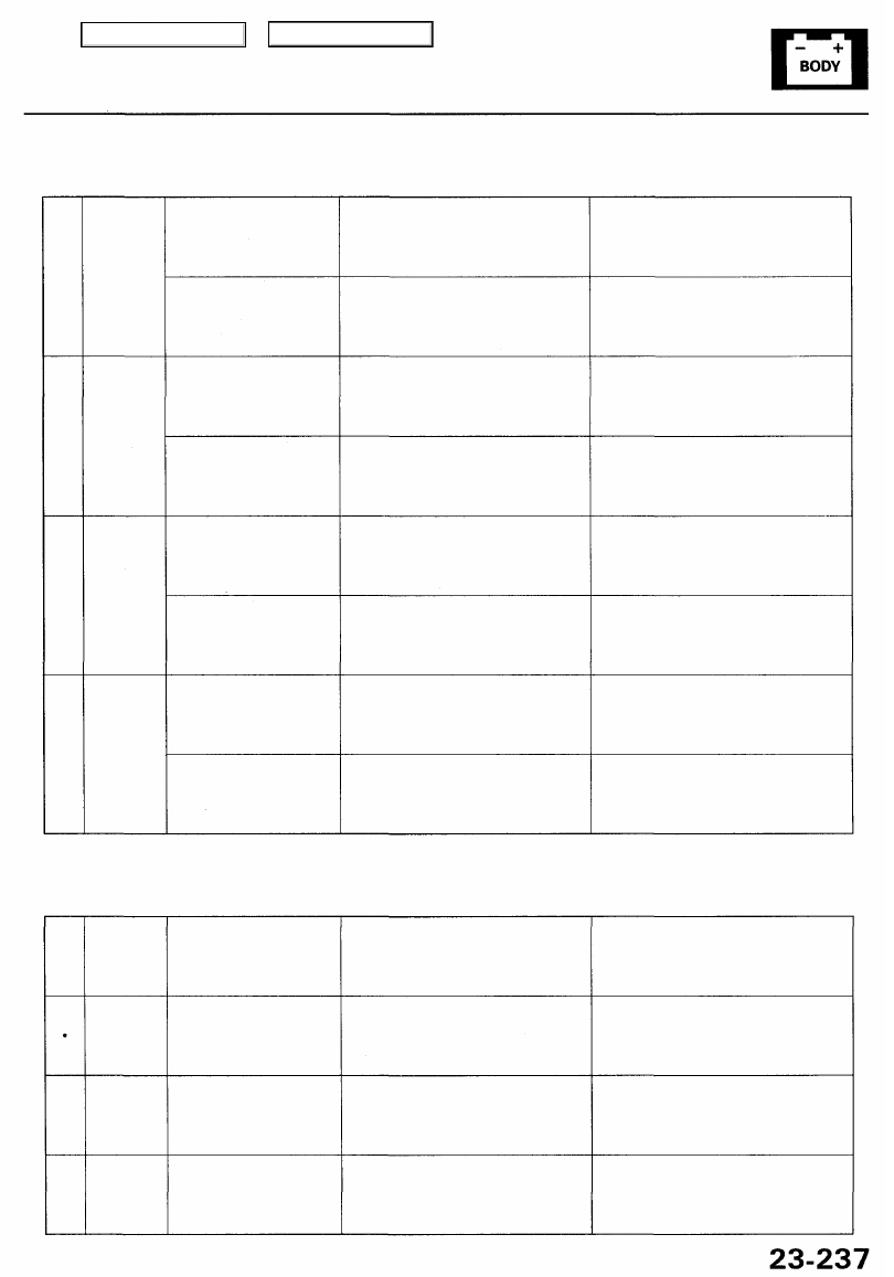
Cavity Wire
Test condition
Test: Desired result
Possible cause if result is not obtained
C8
•
C9
C2
•
C7
C4
•
C11
C3
•
C10
BRN/WHT
*
ORN
GRN
•
BLU/GRN
YEL
•
LT GRN
RED
•
GRY
Connect battery power
to the C9 terminal, and
C8 terminal to the C1
terminal momentarily.
Connect battery power
to the C8 terminal, and
C9 terminal to the C1
terminal momentarily.
Connect battery power
to the C2 terminal, and
C7 terminal to the C6
terminal momentarily.
Connect battery power
to the C7 terminal, and
C2 terminal to the C6
terminal momentarily.
Connect battery power
to the C4 terminal, and
C11 terminal to the C1
terminal momentarily.
Connect battery power
to the C11 terminal, and
C4 terminal to the C1
terminal momentarily.
Connect battery power
to the C3 terminal, and
C10 terminal to the C6
terminal momentarily.
Connect battery power
to the C10 terminal, and
C3 terminal to the C6
terminal momentarily.
Check the front up-down motor
operation:
The motor should run (up)
Check the front up-down motor
operation:
The motor should run (down)
Check the rear up-down motor
operation:
The motor should run (up)
Check the rear up-down motor
operation:
The motor should run (down)
Check the slide motor operation:
The motor should run (forward)
Check the slide motor operation:
The motor should run (backward)
Check the recline motor operation:
The motor should run (forward)
Check the recline motor operation:
The motor should run (backward)
• Faulty front up-down motor
• An open in the wire
• Faulty front up-down motor
• An open in the wire
• Faulty rear up-down motor
• An open in the wire
• Faulty rear up-down motor
• An open in the wire
• Faulty slide motor
• An open in the wire
• Faulty slide motor
• An open in the wire
• Faulty recline motor
• An open in the wire
• Faulty recline motor
• An open in the wire
Reconnect all connectors to the power steering control unit.
Cavity Wire
Test condition
Test: Desired result
Possible cause if result is not obtained
A4
•
B1
A4
B9
A4
•
B2
A4
•
B
10
GRN/BLK
•
YEL/BLK
GRN/BLK
•
WHT
GRN/BLK
•
YEL/GRN
GRN/BLK
•
WHT/RED
Front up-down motor
runs momentarily.
Rear up-down motor
runs momentarily.
Slide motor runs
momentarily.
Recline motor runs
momentarily.
Check for voltage between the
terminals:
The voltage should pulse between
1 V or less and 4 V or more.
Check for voltage between the
terminals:
The voltage should pulse between
1 V or less and 4 V or more.
Check for voltage between the ter-
minals:
The voltage should pulse between
1 V or less and 4 V or more.
Check for voltage between the ter-
minals:
The voltage should pulse between
1 V or less and 4 V or more.
• Faulty front up-down position
sensor
• An open in the wire
• Faulty rear up-down position sensor
• An open in the wire
• Faulty slide position sensor
• An open in the wire
• Faulty recline position sensor
• An open in the wire
Main Menu
Table of Contents
Driving Position Memory System (DPMS)
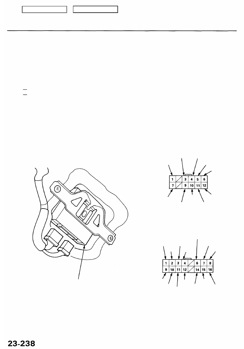
Power Mirror Control Unit Input Test
1. Remove the driver's door panel (see
).
2. Disconnect the power mirror control unit connectors.
3. Inspect the connector and socket terminals to be sure they are all making good contact.
• If the terminals are bent, loose or corroded, repair them as necessary, and recheck the system.
• If the terminals look OK, make the following input tests at the connector.
If a test indicates a problem, find and correct the cause, then recheck the system.
If all the input tests prove OK, substitute a known-good control unit, and recheck the system.
NOTE:
• If all the control unit (steering column, power seat, power mirror) input tests prove OK, disconnect all three
control units, and check for opens or shorts in the communication lines.
• All connector views are from wire side of female terminals.
12P CONNECTOR "A"
BLU/GRN BLU/ORN
LT GRN/RED
RED/WHT
WHT/YEL
BLK/WHT
YEL
BLU
YEL/BLK
BLK
16P CONNECTOR "B"
WHT/YEL ('99 - 01 models)
RED/YEL ('96 - 98 models)
YEL
BRN
YEL
GRN/WHT
GRN
RED/BLK
BRN/WHT
GRY
GRY
BLU
BRN
BLU
BLK
POWER MIRROR CONTROL UNIT
Main Menu
Table of Contents
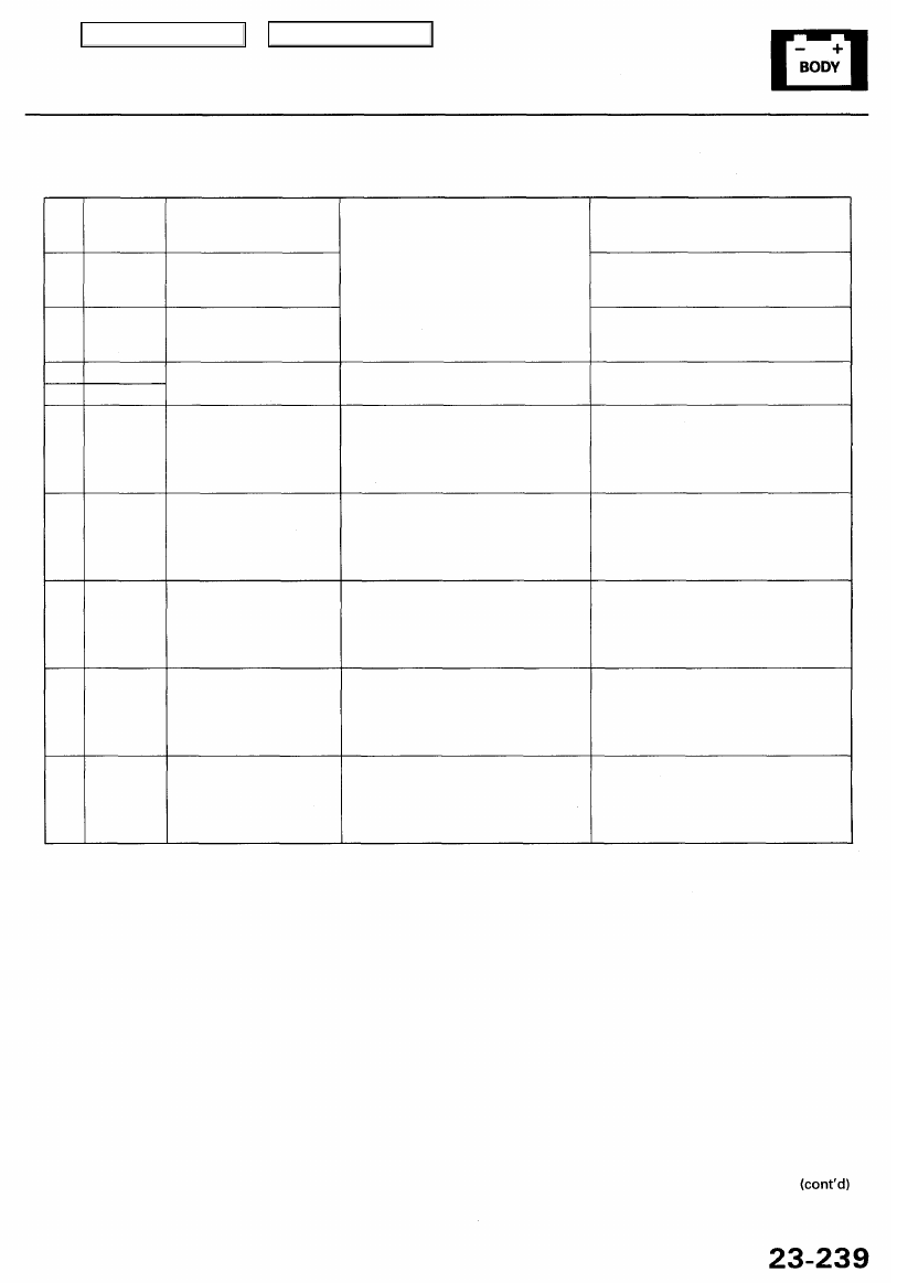
Cavity Wire
Test condition
Test: Desired result
Possible cause if result is not obtained
A6
B1
A11
A12
B9
A3
A4
A5
A9
A10
WHT/YEL
RED/YEL
(WHT/YEL)
YEL/BLK
BLK
BLK
BLU/GRN
BLU/ORN
RED/WHT
YEL
BLU
Under all conditions
Under all conditions
Ignition switch ON (II)
Under all conditions.
Ignition switch ON (II),
and power mirror selec-
tor switch to right, then
press the power mirror
switch "Right"
Ignition switch ON (II),
and power mirror selec-
tor switch to right, then
press the power mirror
switch "Left" or "Down"
Ignition switch ON (II),
and power mirror selec-
tor switch to right or left,
then press the power
mirror switch "UP"
Ignition switch ON (II),
and power mirror selec-
tor switch to left, then
press the power mirror
switch "Right"
Ignition switch ON (II),
and power mirror selec-
tor switch to left, then
press the power mirror
switch "Left" or "Down"
Check for voltage to ground:
There should be battery voltage.
Check for continuity to ground:
There should be continuity.
Check for voltage to ground:
There should be battery voltage.
Check for voltage to ground:
There should be battery voltage.
Check for voltage to ground:
There should be battery voltage.
Check for voltage to ground:
There should be battery voltage.
Check for voltage to ground:
There should be battery voltage.
• Blown No. 56 (7.5 A) fuse in the under-
hood fuse/relay box
• An open in the wire
• Blown No. 54 (20 A) or No. 56 (7.5 A)
fuse in the under-hood fuse/relay box
• An open in the wire
• Blown No. 19 (7.5 A) fuse in the under-
dash fuse/relay box
• An open in the wire
• Poor ground (G401, G402 or G251)
• An open in the wire
• Blown No. 19 (7.5 A) fuse in the under-
dash fuse/relay box
• Faulty power mirror switch
• An open in the wire
• Blown No. 19 (7.5 A) fuse in the under-
dash fuse/relay box
• Faulty power mirror switch
• An open in the wire
• Blown No. 19 (7.5 A) fuse in the under-
dash fuse/relay box
• An open in the wire
• Blown No. 19 (7.5 A) fuse in the under-
dash fuse/relay box
• Faulty power mirror switch
• An open in the wire
• Blown No. 19 (7.5 A) fuse in the under-
dash fuse/relay box
• Faulty power mirror switch
• An open in the wire
Main Menu
Table of Contents
Driving Position Memory System (DPMS)
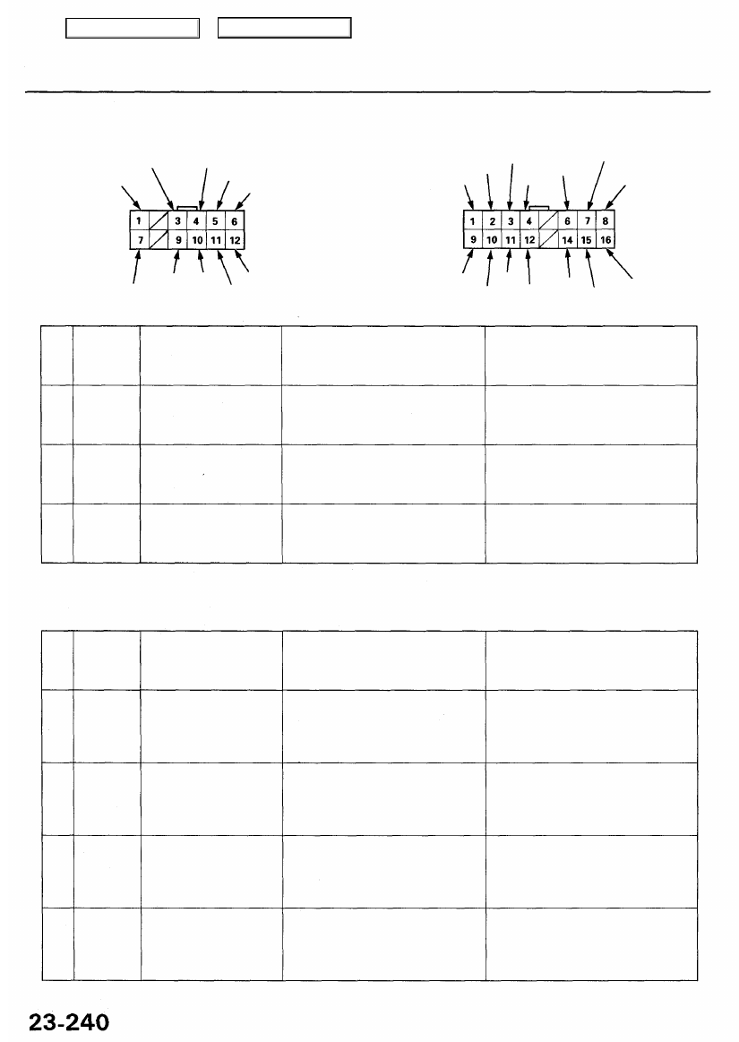
Power Mirror Control Unit Input Test (cont'd)
12P CONNECTOR "A"
BLU/GRN BLU/ORN
RED/WHT
WHT/YEL
16P CONNECTOR "B"
BRN
YEL
GRN
RED/YEL
GRN/WHT
RED/BLK
Cavity
BLK/WHT
Wire
BLK
YEL/BLK
Test condition
Test: Desired result
BRN/WHT
BLU BLU GRY
Possible cause if result is not obtained
B3
•
B4
B3
•
B12
B2
•
B11
B10
*
B11
BRN
•
YEL
BRN
•
BLU
YEL
•
BRN
BLU
•
BRN
Connect battery power
to the B3 terminal, and
B4 terminal to the B9
terminal momentarily.
Connect battery power
to the B3 terminal, and
B12 terminal to the B9
terminal momentarily.
Connect battery power
to the B11 terminal, and
B2 terminal to the B9
terminal momentarily.
Connect battery power
to the B11 terminal, and
B10 terminal to the B9
terminal momentarily.
Check the right power mirror
actuator operation:
The mirror should swing left.
Check the right power mirror
actuator operation:
The mirror should tilt down.
Check the left power mirror
actuator operation:
The mirror should swing left.
Check the left power mirror
actuator operation:
The mirror should tilt down.
• Faulty right power mirror actuator
• An open in the wire
• Faulty right power mirror actuator
• An open in the wire
• Faulty left power mirror actuator
• An open in the wire
• Faulty left power mirror actuator
• An open in the wire
Reconnect all connectors to the power mirror control unit.
Cavity Wire
Test condition
Test: Desired result
Possible cause if result is not obtained
B8
•
B16
B7
•
B16
B15
•
B16
B6
•
B16
B14
•
B16
RED/BLK
•
BRN/WHT
GRN
•
BRN/WHT
GRY
•
BRN/WHT
GRN/WHT
•
BRN/WHT
GRY
•
BRN/WHT
Ignition switch ON (II)
NOTE: Connect all
mirror control unit
connectors.
Ignition switch ON (II)
NOTE: Connect all
mirror control unit
connectors.
Ignition switch ON (II)
NOTE: Connect all
mirror control unit
connectors.
Ignition switch ON (II)
NOTE: Connect all
mirror control unit
connectors.
Ignition switch ON (II)
NOTE: Connect all
mirror control unit
connectors.
Check for voltage between the
terminals:
There should be about 5 V.
Check for voltage between the
terminals:
The voltage should change from
about 1 V to 3 V when the right
mirror swings from left to right.
Check for voltage between the
terminals:
The voltage should change from
about 1 V to 3 V when the right
mirror tilts from up to down.
Check for voltage between the
terminals:
The voltage should change from
about 1 V to 3 V when the left mir-
ror swings from right to left.
Check for voltage between the
terminals:
The voltage should change from
about 1 V to 3 V when the left mir-
ror tilts from up to down.
• Faulty power mirror position
sensors
• An open in the wire
• Faulty right power mirror position
sensor
• An open in the wire
• Faulty right power mirror position
sensor
• An open in the wire
• Faulty left power mirror position
sensor
• An open in the wire
• Faulty left power mirror position
sensor
• An open in the wire
YEL
GRY
BRN
BLK
YEL BLU
LT GRN/RED
Main Menu
Table of Contents
Нет комментариевНе стесняйтесь поделиться с нами вашим ценным мнением.
Текст