Acura RL (1996-2004 year). Manual — part 641
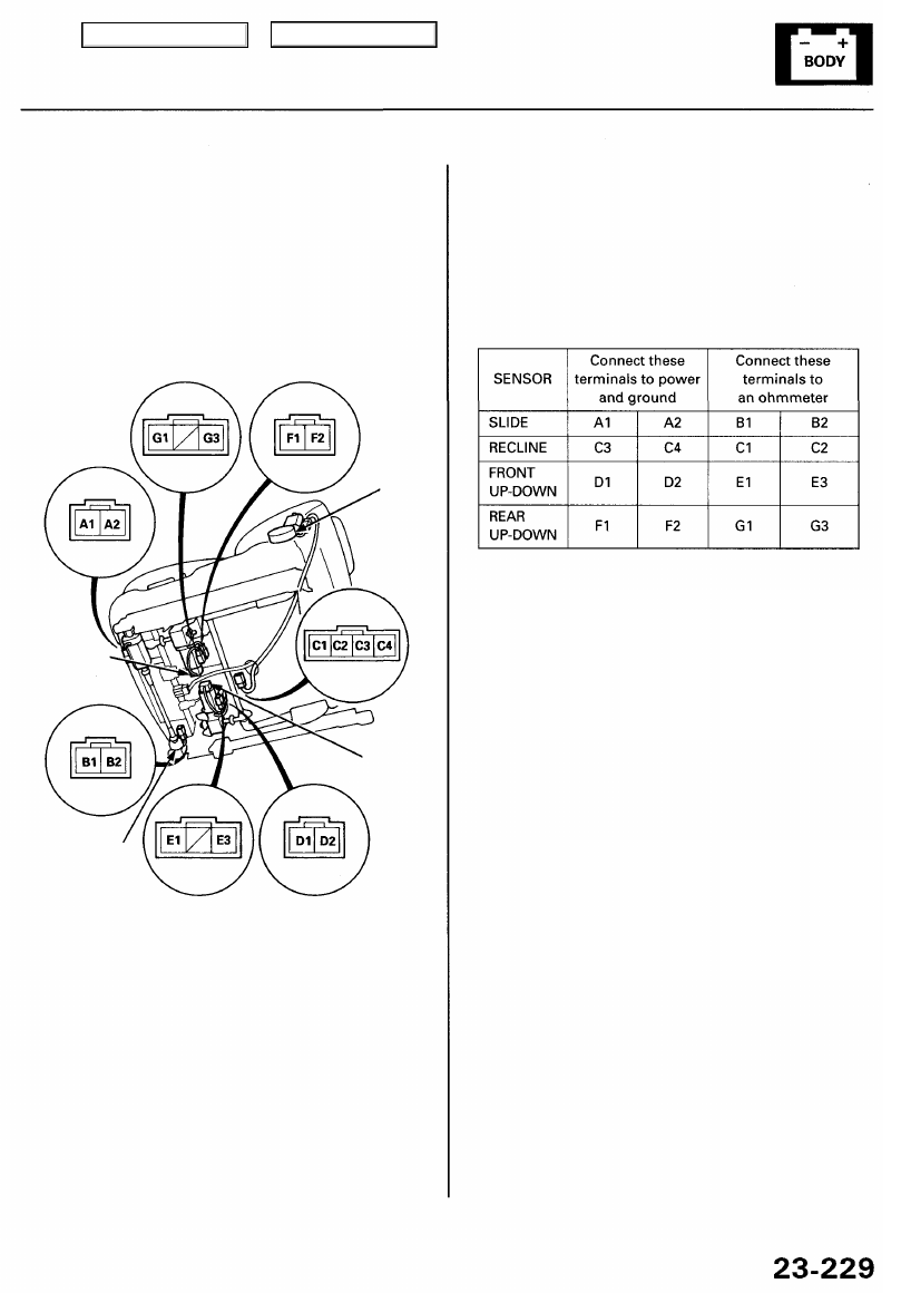
Driver's Power Seat Position Sensor Test
CAUTION: Be careful not to damage the seat, interior
trim or body.
1. Remove the driver's seat (see
).
2. Disconnect the connector from each power seat
memory sensor and motor.
RECLINE
POSITION
SENSOR
REAR
UP-DOWN
POSITION
SENSOR
FRONT
UP-DOWN
POSITION
SENSOR
SLIDE
POSITION
SENSOR
NOTE: If a motor does not run, reverse power and
ground. If the motor still does not run, replace the
motor.
3. Test the sensor by connecting power and ground to
the motor, and connect an analog ohmmeter test
leads to the sensor connector.
The needle in the ohmmeter should move from left
to right.
CAUTION: When a motor stops running, discon-
nect power immediately.
Main Menu
Table of Contents
Driving Position Memory System (DPMS)
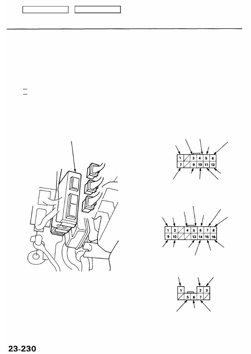
Steering Column Control Unit Input Test
1. Remove the dashboard lower cover (see
).
2. Disconnect the steering column control unit connectors.
3. Inspect the connector and socket terminals to be sure they are all making good contact.
• If the terminals are bent, loose or corroded, repair them as necessary, and recheck the system.
• If the terminals look OK, make the following input tests at the connector.
If a test indicates a problem, find and correct the cause, then recheck the system.
If all the input tests prove OK, substitute a known-good control unit, and recheck the system.
NOTE:
• If all the control unit (steering column, power seat, power mirror) input tests prove OK, disconnect all three
control units, and check for opens or shorts in the communication lines.
• All connector views are from wire side of female terminals.
STEERING COLUMN CONTROL UNIT
12P CONNECTOR "A"
BLK/WHT
BLK/BLU
BLU/WHT
BLK
RED
WHT/YEL
RED/GRN
BLU/WHT
BLK/YEL
LT GRN/RED
16P CONNECTOR "B"
BLU
GRY
LT BLU
RED/BLK
BLU/ORN
BLU/WHT
YEL/WHT
YEL/BLU
BLU/YEL
BLU/BLK
RED
BRN
PNK
8P CONNECTOR "C"
BLK
BRN RED/YEL
LT GRN
PNK/BLK
GRY/RED
Main Menu
Table of Contents
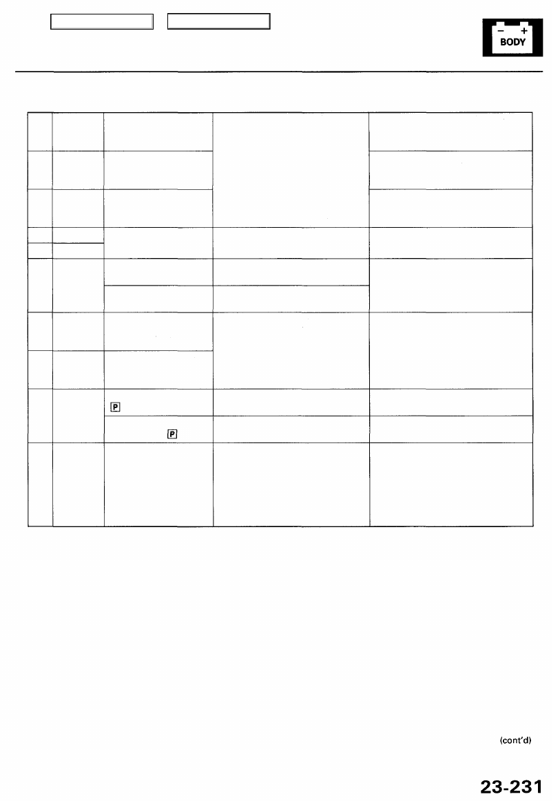
Cavity Wire
Test condition
Test: Desired result
Possible cause if result is not obtained
A5
A6
C3
A12
C1
A4
A3
A9
A10
A11
BLK/YEL
WHT/YEL
RED/YEL
BLK
BLK
BLU/WHT
RED/GRN
RED
BLK/BLU
BLU/WHT
Ignition switch ON (II)
Under all conditions
Under all conditions
Under all conditions
Ignition key inserted
into the ignition switch
Ignition key removed
from the ignition switch
Under all conditions
(observe memo
1 indicator)
Under all conditions
(observe memo
2 indicator)
Shift lever in position
Shift lever in any other
position than
Raise the front of the
vehicle support it with
safety stands, put it in
neutral, and rotate one
wheel with the other
blocked, then turn the
ignition switch ON (II).
Check for voltage to ground:
There should be battery voltage.
Check for continuity to ground:
There should be continuity.
Check for voltage to ground:
There should be 1 V or less.
Check for voltage to ground:
There should be 4 V or more.
Attach to ground:
The indicator should come on.
Check for voltage to ground:
There should be 1 V or less.
Check for voltage to ground:
There should be 4 V or more.
Check for voltage to ground:
The voltage should pulse from 0 V
to about 5 V or more.
• Blown No. 20 (20 A) fuse in the
under-dash fuse/relay box
• An open in the wire
• Blown No. 56 (7.5 A) fuse in the
under-hood fuse/relay box
• An open in the wire
• Blown No. 54 (20 A) fuse in the
under-hood fuse/relay box
• An open in the wire
• Poor ground (G401, G402 or G251)
• An open in the wire
• Poor ground (G401, G402 or G251)
• Faulty ignition key switch
• An open in the wire
• Blown No. 56 (7.5 A) fuse in the
under-hood fuse/relay box
• Faulty LED in the driving position
memory switch
• An open in the wire
• Faulty transmission range switch
• An open in the wire
• Faulty transmission range switch
• An open in the wire
• Faulty vehicle speed sensor (VSS)
• An open in the wire
Main Menu
Table of Contents
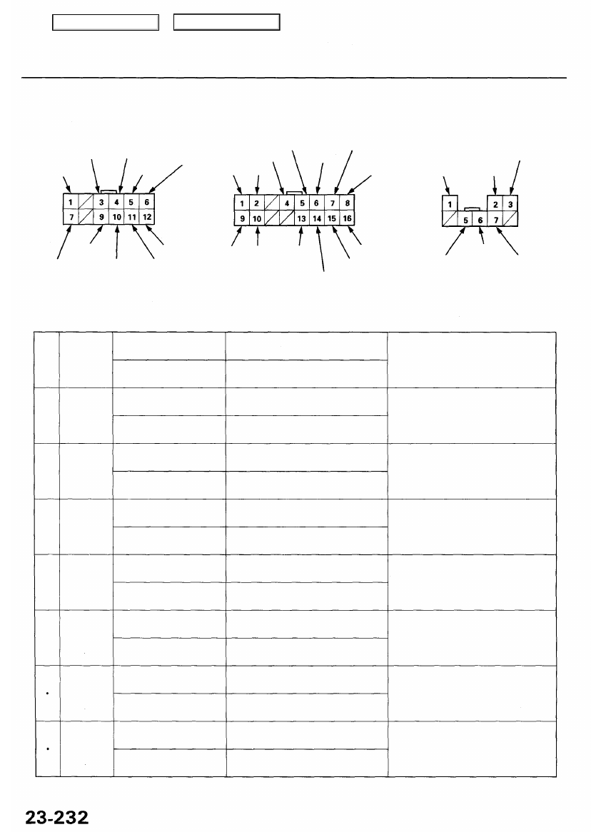
Driving Position Memory System (DPMS)
Steering Column Control Unit Input Test (cont'd)
12P CONNECTOR "A"
RED/GRN BLU/WHT
WHT/YEL
BLK/YEL
PNK BRN
RED
YEL/BLU
BLU/YEL
BLU/BLK
8P CONNECTOR "C"
RED/YEL
BLK
BRN
GRY/RED
LT GRN
Cavity Wire
Test condition
Test: Desired result
Possible cause if result is not obtained
B4
B5
*
B16
B6
*
B16
B7
•
B16
B8
•
B16
B13
•
B16
B14
B16
B15
B16
LT BLU
RED/BLK
•
YEL/BLU
BLU/ORN
•
YEL/BLU
BLU/WHT
•
YEL/BLU
YEL/WHT
•
YEL/BLU
RED
•
YEL/BLU
BLU/BLK
•
YEL/BLU
BLU/YEL
•
YEL/BLU
Auto switch ON
Auto switch OFF
Extend switch ON
Extend switch OFF
Up switch ON
Up switch OFF
Position button 1
pressed
Position button 1
released
MEMO button pressed
MEMO button released
Retract switch ON
Retract switch OFF
Down switch ON
Down switch OFF
Position button 2
pressed
Position button 2
released
Check for continuity to ground:
There should be continuity.
Check for continuity to ground:
There should be no continuity.
Check for continuity:
There should be continuity.
Check for continuity:
There should be no continuity.
Check for continuity:
There should be continuity.
Check for continuity:
There should be no continuity.
Check for continuity:
There should be continuity.
Check for continuity:
There should be no continuity.
Check for continuity:
There should be continuity.
Check for continuity:
There should be no continuity.
Check for continuity:
There should be continuity.
Check for continuity:
There should be no continuity.
Check for continuity:
There should be continuity.
Check for continuity:
There should be no continuity.
Check for continuity:
There should be continuity.
Check for continuity:
There should be no continuity.
• Faulty steering column switch
• An open in the wire
• Faulty steering column switch
• An open in the wire
• Faulty steering column switch
• An open in the wire
• Faulty driving position memory
switch
• An open in the wire
• Faulty driving position memory
switch
• An open in the wire
• Faulty steering column switch
• An open in the wire
• Faulty steering column switch
• An open in the wire
• Faulty driving position memory
switch
• An open in the wire
16P CONNECTOR "B"
RED/BLK
BLU GRY
LT BLU
BLU/ORN
BLU/WHT
YEL/WHT
PNK/BLK
BLK/WHT BLK/BLU BLU/WHT
BLK
RED
LT GRN/RED
Main Menu
Table of Contents
Нет комментариевНе стесняйтесь поделиться с нами вашим ценным мнением.
Текст