Mazda Transaxle FN4A-EL. Manual — part 7
K1–20
AUTOMATIC TRANSAXLE
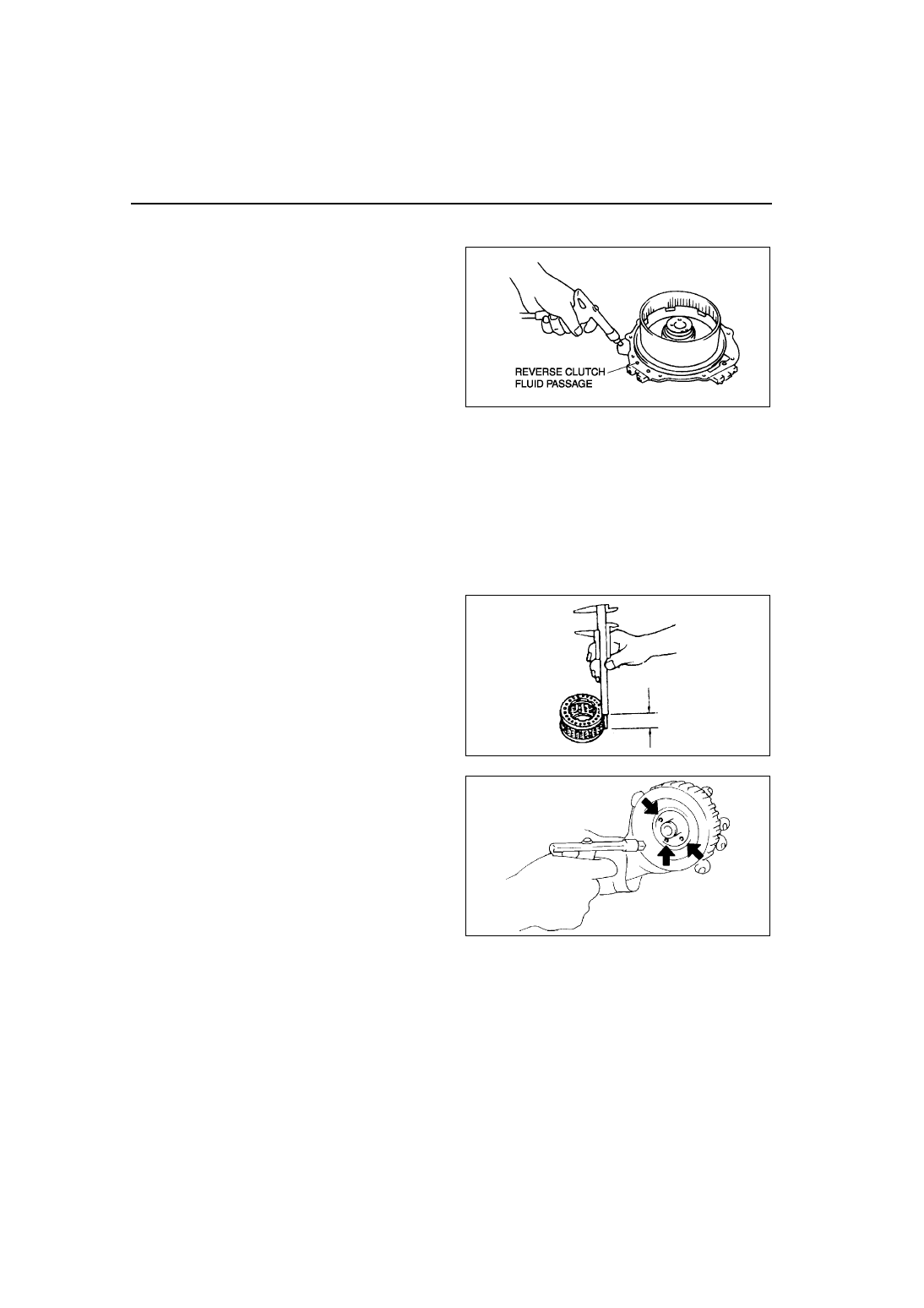
Reverse Piston Disassembly Note
1. Set the 2-4 brake drum onto the end cover.
2. Remove the reverse piston from the 2-4 brake
drum by applying compressed air through the
fluid passage.
Air pressure
392 kPa {4.0 kgf/cm
2
, 57 psi} max.
Assembly Procedure
1. Measure the facing thickness in three places and calculate the average value.
Drive plate part number: FN11 19 370
Standard: 1.60 mm {0.063 in}
Minimum: 1.45 mm {0.057 in}
Drive plate part number: FNE1 19 370
Standard: 2.55 mm {0.100 in}
Minimum: 2.40 mm {0.094 in}
2. If not within the specification, replace the drive plates.
3. Measure the free length of the spring and inspect
for deformation.
Spring free length
Standard: 17.0 mm {0.669 in}
Minimum: 15.0 mm {0.591 in}
4. If not within the specification, replace the spring
and retainer.
5. Verify that there is airflow when applying
compressed air through the fluid passage of 3-4
clutch drum.
Air pressure
392 kPa {4.0 kgf/cm
2
, 57 psi} max.
6. Replace the 3-4 clutch drum if damaged or
malfunctioning.
A6E5714A037
X3U517AC8
X3U517AC9
AUTOMATIC TRANSAXLE
K1–21
K1
7. Verify that there is airflow when applying
compressed air through the fluid passage of 2-4
brake drum.
Air pressure
392 kPa {4.0 kgf/cm
2
, 57 psi} max.
8. Replace the 2-4 brake drum if damaged or
malfunctioning.
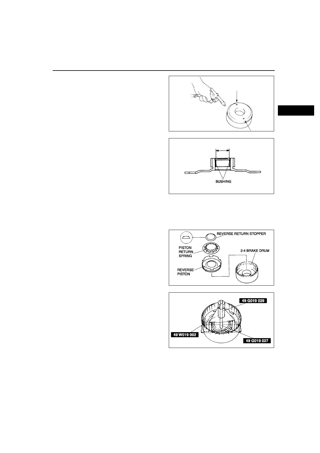
9. Measure the bushing of the rear sun gear.
Bushing inner diameter
Standard:
26.400—26.421 mm {1.03937—1.04019
in}
Maximum: 26.441 mm {1.04098 in}
10. If not as specified, replace the rear sun gear
plate.
11. Install the reverse clutch.
Caution
••••
Installing the reverse clutch piston may
damage its seal. Carefully install the reverse clutch piston by pushing evenly around the
circumference.
(1) Apply ATF to the circumference of the reverse clutch piston seal, and install the piston into the 2-4 brake
drum.
(2) Install the piston return spring and reverse
return stopper to the reverse piston.
(3) Install the snap ring and the SSTs to the 2-4
brake drum as shown.
Caution
••••
Depress the piston return spring only
enough to install the snap ring.
Overpressing will damage the piston
return spring assembly edges.
(4) Compress the piston return spring.
(5) Install the snap ring.
(6) Remove the SSTs.
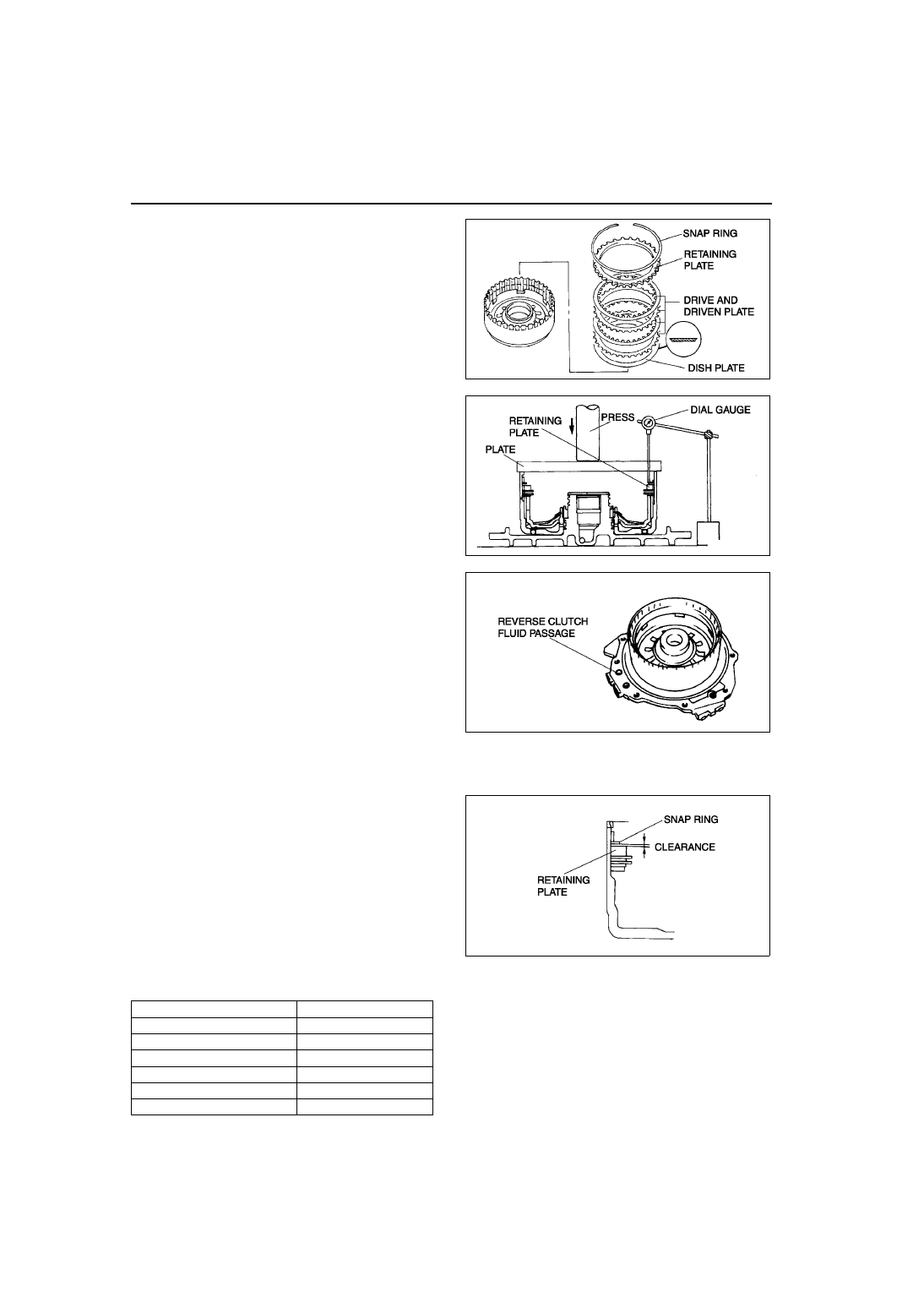
(7) Install the dish plate.
(8) Install the drive and driven plates in the
following order.
Driven-Drive-Driven-Drive
X3U517ACA
A6E5714A038
A6E5714A039
A6E5714A036
K1–22
AUTOMATIC TRANSAXLE
(9) Install the retaining plate.
12. Measure the reverse clutch clearance.
(1) Install the reverse clutch into the end cover,
and set the dial gauge.
(2) Secure the reverse clutch by lightly pressing
down with a press, etc.
(3) Apply compressed air to the part indicated in
the figure and let the reverse clutch piston
stroke three times.
Air pressure
392—441 kPa {4.0—4.5 kgf/cm
2
, 57—63 psi}
(4) Apply compressed air and operate the
reverse clutch piston. Read the value when
the indicator of the dial gauge stops.
(5) Release the compressed air and read the dial
gauge when the reverse clutch piston is not
operating.
(6) Calculate the reverse clutch clearance
according to the following formula:
step (4) value – step (5) value = Reverse clutch clearance.
(7) Measure the clearances at four locations (90
°
apart) by following the steps from (3) to (6).
Verify that the average value is within the
specification below.
Reverse clutch clearance
1.00—1.03 mm {0.039—0.051 in}
(8) If not as specified, remove the snap ring and
measure its thickness.
(9) Add the thickness to the average value
calculated in step (7), and select the snap ring
whose range includes the value.
Snap ring sizes
Range mm {in}
Snap ring sizes mm {in}
2.250—2.450 {0.089—0.096}
1.2 {0.047}
2.450—2.650 {0.096—0.104}
1.4 {0.055}
2.650—2.850 {0.104—0.112}
1.6 {0.063}
2.850—3.050 {0.112—0.120}
1.8 {0.071}
3.050—3.250 {0.120—0.128}
2.0 {0.079}
3.250—3.450 {0.128—0.136}
2.2 {0.087}
A6E5714A040
A6E5714A041
A6E5714A042
A6E5714A043
AUTOMATIC TRANSAXLE
K1–23
K1
(10)Install the selected snap ring and perform steps (2) to (7) again. Verify that the calculated value satisfies
the clearance specification.
13. Inspect the reverse clutch operation.
(1) Install the 2-4 brake drum to the end cover.
(2) Inspect the reverse clutch operation by
applying compressed air as shown.
Air pressure
392—441 kPa {4.0—4.5 kgf/cm
2
, 57—63 psi}
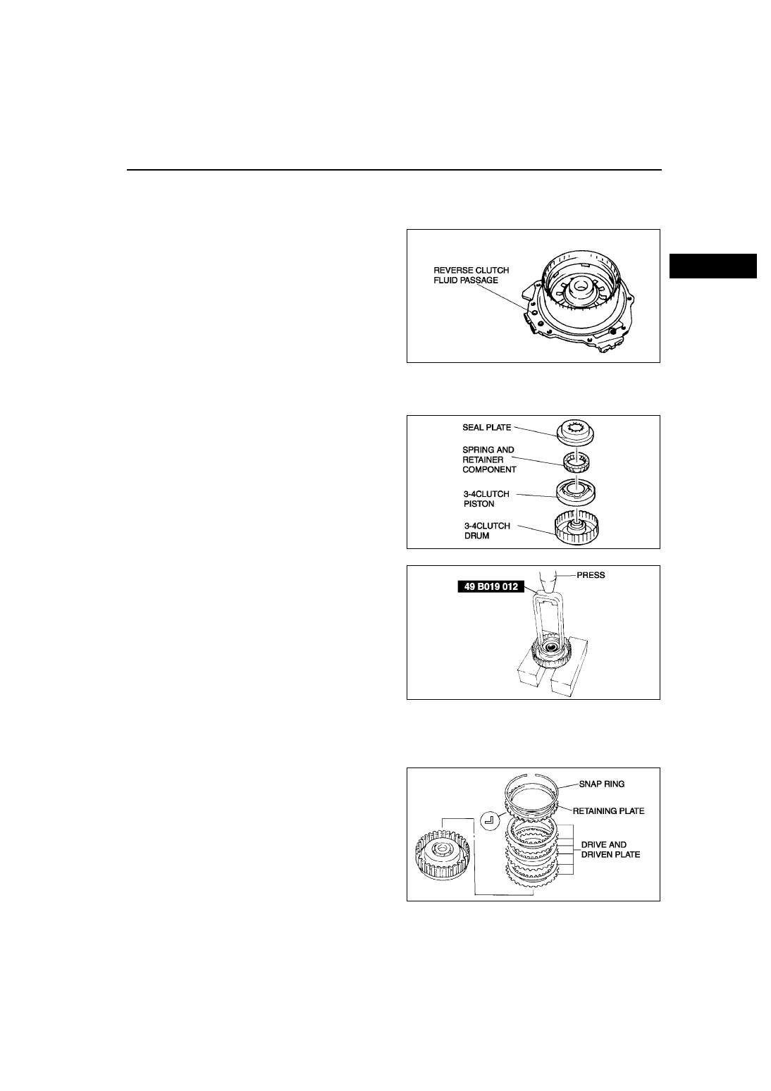
14. Install the 3-4 clutch.
Caution
••••
Installing the 3-4 clutch piston may
damage its seal. Carefully install the 3-4
clutch piston by pushing evenly around
the circumference.
(1) Apply ATF to the circumference of the 3-4 clutch piston seal, and install the piston in to the 3-4 clutch drum.
(2) Install the spring and retainer.
(3) Apply ATF to the 3-4 seal plate, and install it
onto the 3-4 clutch drum.
(4) Install the SST as shown.
Caution
••••
Depress the 3-4 seal plate only enough to
install the snap ring. Overpressing will
damage the 3-4 seal plate assembly
edges.
(5) Compress the spring and retainer component
and 3-4 seal plate.
(6) Install the snap ring.
(7) Remove the SST.
(8) Install the drive and driven plates in the
following order.
Driven-Drive-Driven-Drive-Driven-Drive
(9) Install the retaining plate.
DRIVE PLATE PART NUMBER:FN11 19 370
A6E5714A042
A6E5714A044
A6E5714A045
A6E5714A046
Нет комментариевНе стесняйтесь поделиться с нами вашим ценным мнением.
Текст