Mazda Training manual — part 5

Powertrain Engines
Cylinder Block
•
The cylinder block features a bearing support frame, in which the main bearing caps are
integrated. Cylinder block and bearing support frame are matched to each other, i.e. they
cannot be replaced separately. If one of the components exceeds the specification, the
cylinder block must be replaced as a complete unit.
•
The main bearing cap bolts are torque-to-yield bolts, which must be tightened in several
stages (refer to the workshop manual for details).
L1001.4_01002
1
Cylinder block
2
Bearing support frame
Curriculum Training
01-7

Engines Powertrain
Pistons
•
The piston skirt is coated to reduce friction between the piston and the cylinder.
•
Piston, piston pin and connecting rod are shrinkage fitted and cannot be disassembled. If
one of the components exceeds the specification, the piston/ connecting rod assembly
has to be replaced as a complete unit.
L1001.4_01003
1
Engine front side
3
Valve recesses
2
Arrow indicating the installation direction
01-8 Curriculum
Training
Powertrain Engines
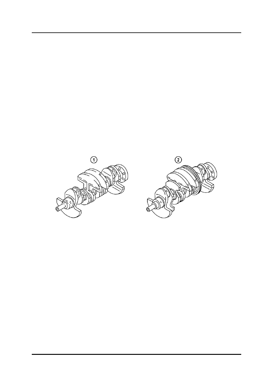
Crankshaft
•
The crankshaft for the L8 and LF engine has four counterweights, while the crankshaft
for the L3 engine has eight counterweights.
•
In addition, the crankshaft for the L3 engine is equipped with a drive gear for the
balancer shafts.
•
The crankshaft features no key for the installation of the crankshaft sprocket and the
crankshaft pulley, i.e. solely the clamping force of the lock bolt secures both components
on the crankshaft.
•
The crankshaft pulley has a pulse wheel for the CKP (Crankshaft Position) sensor
signals. For this reason, the crankshaft pulley must be fixed to the engine front cover
using a detent bolt (M6 x 1.0) before tightening the crankshaft pulley lock bolt.
•
The crankshaft pulley lock bolt is a torque-to-yield bolt, which must be tightened in
several stages (refer to the workshop manual for details).
NOTE: The crankshaft pulley lock bolt must not be re-used.
L1001.4_01004
1
Crankshaft (L8, LF engine)
2
Crankshaft (L3 engine)
Curriculum Training
01-9
Engines Powertrain
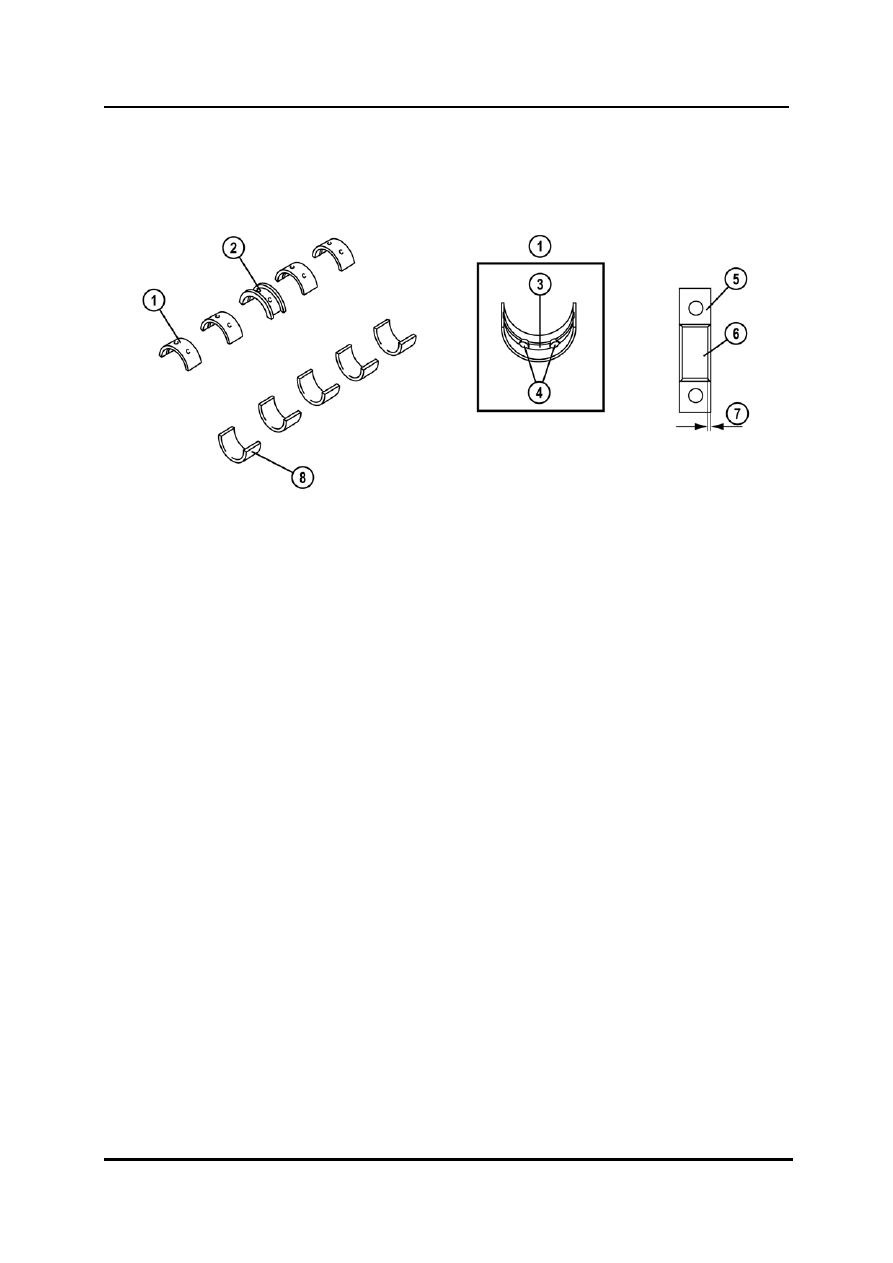
•
There is no positioning tab for locating the upper and lower bearing in the main journal.
For installing the main bearing shells (upper and lower), they have to be measured and
attached so that they are positioned in the center of the main bearing cap (refer to the
workshop manual for details).
L1001.4_01005
1
Upper main bearing shell
5
Main bearing cap
2
Thrust bearing
6
Main bearing shell
3
Upper main bearing oil groove
7
Specified measurement
4
Oil holes
8
Lower main bearing shell
01-10 Curriculum
Training
Нет комментариевНе стесняйтесь поделиться с нами вашим ценным мнением.
Текст