Great Wall Florid. Manual — part 6
GWFLORID Maintenance Manual
22
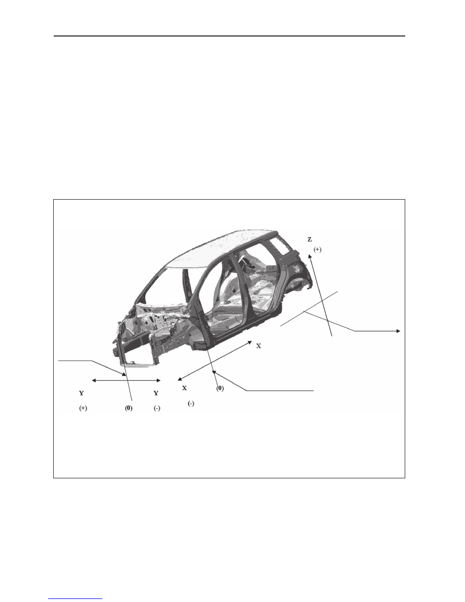
Imaginary
reference line
Front wheel center line
Vehicle center line
"Z" represents the imaginary
reference line [below reference
line ("OZ" line of the design
diagram) 400 mm]
Vehicle Body's Basic Calibration Measurements
This section shows the basic parameters of the overall vehicle. Please refer to this section when servicing or
repairing.
• All figures used to express measurements are actual figures.
• Measuring points are taken from the center of the mounting holes.
• When using the gauge, adjust the two measuring needles until they reach an equal length, then check
the measuring needle and the gauge itself to ensure there are no gaps.
• When using measuring tape, make sure not to stretch, twist, or bend it.
• The asterisk (*) symbol after a numerical measurement value indicates that the other side's
symmetrical position is of equal value.
• Coordinates of the measuring points refer to the distances measured between the point and "X", "Y",
and "Z" standard lines.
• The left & right symmetry points of a measuring point's coordinate represent a coordinate point on the
left side, and that the right and left side are symmetrical.
23
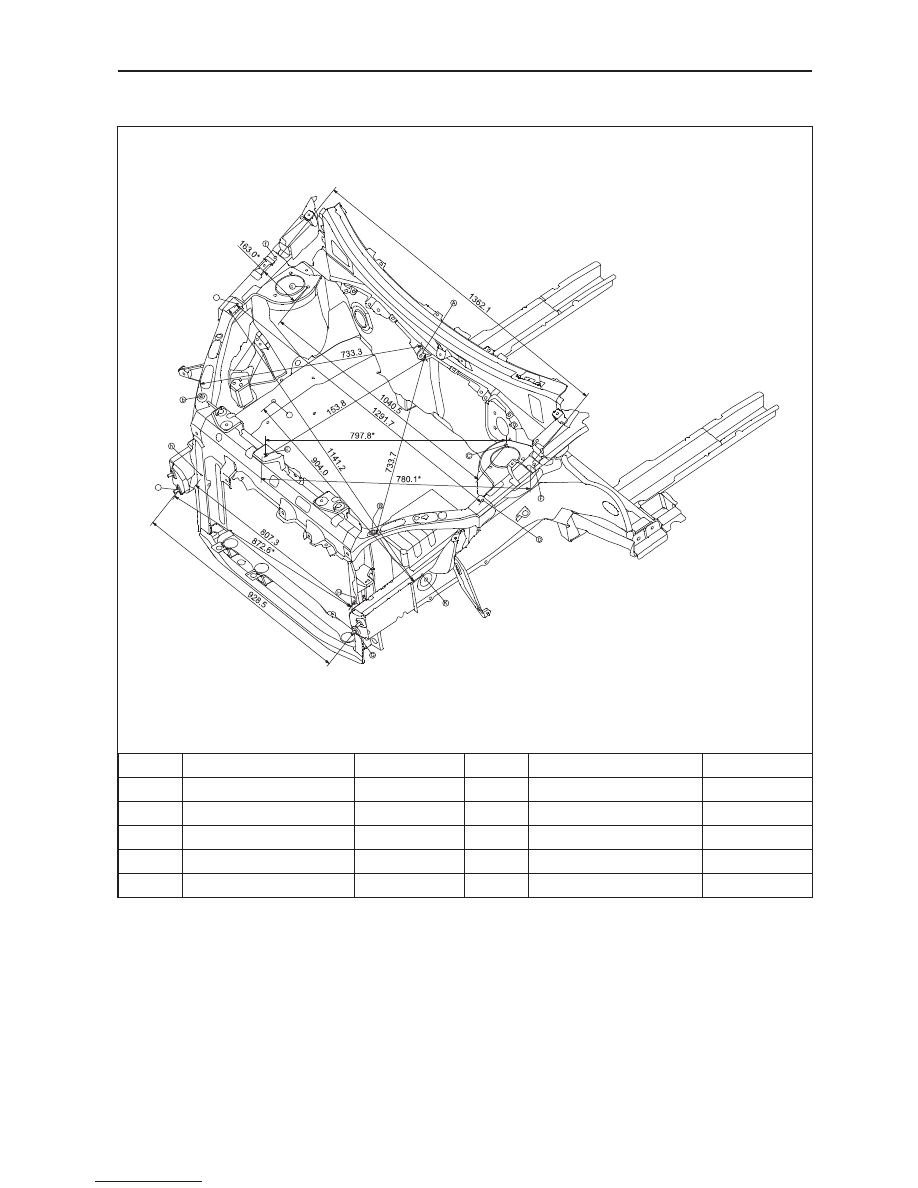
Overall Parameters
Engine Compartment
Mark
Axis (X, Y, Z)
Diameter (mm)
Mark
Axis (X, Y, Z)
Diameter (mm)
A
(115.2, 0.4, 701.5)
Ф10
B
(-461.2, -447.6, 627.7)
Ф8
C
(56.5, -520.3, 698.8)
Ф11
D
(-143.9, -645.9, 690.9)
Ф8
E
(-506.2, -45.0, 679.1)
Ф9
F
(-52.3, -681.0, 725.3)
Ф10
G
(-606.8, -464.3, 290.6)
Ф8.5
H
(-548.7, -403.6, 359.8)
Ф8
J
(-188.4, 467.5, 387.9)
Ф13
K
(-319.0, -425.0, 327.5)
Ф14
GWFLORID Maintenance Manual
24
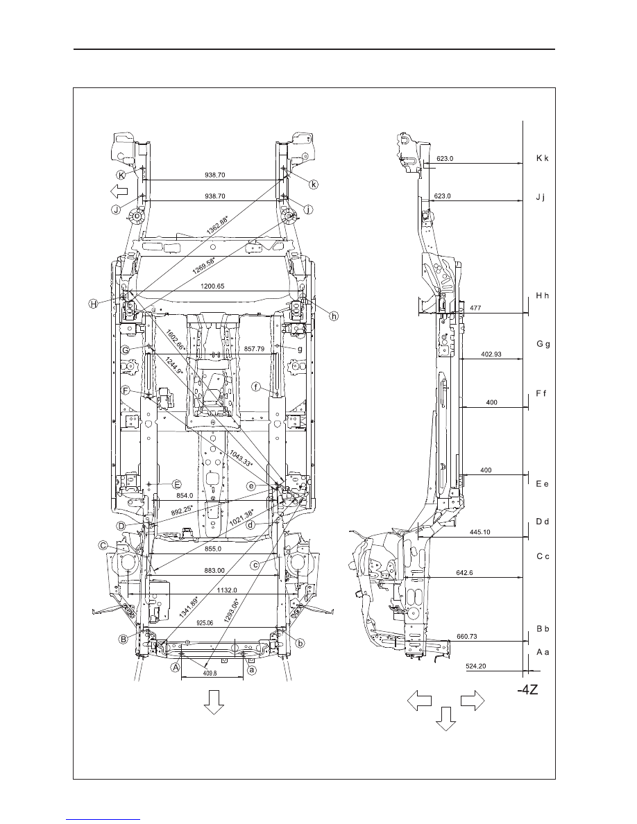
Chassis
LH
side
Front
Front
Upper
Lower
Unit: mm
25
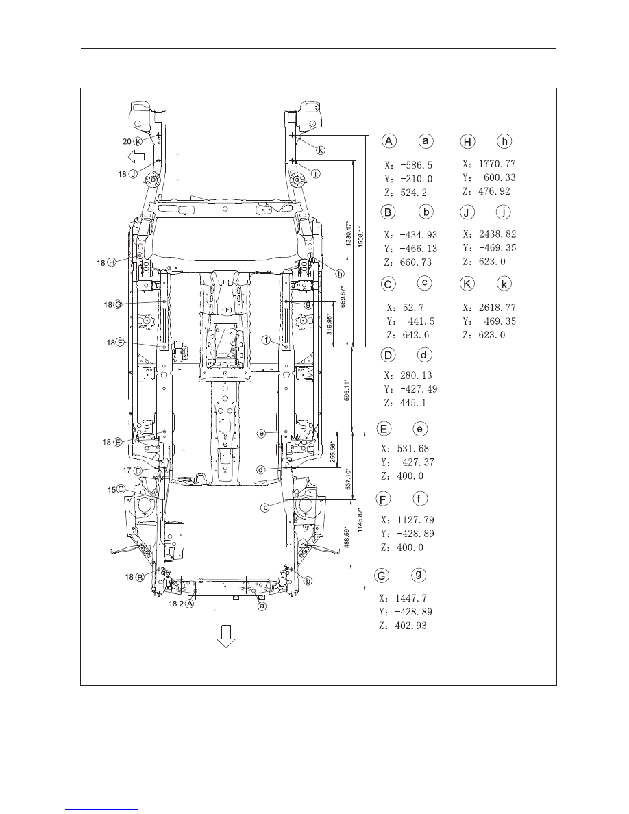
Overall Parameters
Chassis (Continued)
LH
side
Ф
Ф
Ф
Ф
Ф
Ф
Ф
Ф
Ф
Ф
Front
Unit: mm
Axis
Axis
Нет комментариевНе стесняйтесь поделиться с нами вашим ценным мнением.
Текст